Bullnose Garage is a hands-on journey into classic Ford truck restoration. Follow along as I bring new life to my 1985 F-150 and 1982 Bronco, one wrench turn at a time.
Bullnose Garage is a hands-on journey into classic Ford truck restoration. Follow along as I bring new life to my 1985 F-150 and 1982 Bronco, one wrench turn at a time.
Not sure what engine to use for your build? Check here first.
Check this out!
Support The Garage!
Like the builds? Want to see what happens behind the scenes? Join the crew on Patreon for early access, sneak peeks, more rants, and shop-floor chaos you won’t see on YouTube. Every little bit keeps the cameras rolling. Go to patreon.com/BullnoseGarage
Ask Bullnose Bill!
Confused? Need help? Need information? If you have a Bullnose related question that isn't answered by the Bullnose Garage website or YouTube channel, then you can ask Bullnose Bill, our resident AI Bullnose Ford specialist! Humans are overrated anyway.
Bullnose Merch
Looking to show your pride for your Bullnose Truck or Bronco? Check out the Bullnose Garage Merch Store! BNG has designs for both Broncos and F-Series trucks, specially made for enthusiasts like you. Get a shirt, mug, hat, or sticker and show off your project to the world!
Cold wind whispers through the cracks in the door. Star lights flicker like the dawn a thousand times before. Frost climbs steadily up the windows at night. The old folk glow soft in that familiar Christmas light.
Tools on the bench and a chill in the shop. I got a list of parts I’ve wanted in a drawer that time forgot. While the whole world sleeps under winter’s wide appeal, this little garage is where the season feels real. Snow piled still on a cold December night, wrapped up in the glow of Christmas lights. A little rust, a little hope, and a whole lot of feel. Yeah. Christmas to me is snow tires and steel.
The heater’s humming, but it barely blows warm. Still I’m out here wrenching through another winter storm. These long nights settle in when the daylight starts to fade, but my shop brightens up the dark. Neighbors may shake their heads at me working alone, but this place turns the holidays into something of my own. Every bolt I crack loose, every part that I reveal feels a bit more like Christmas wrapped in chrome and steel. Snow tires and steel on a cold December night, warming up in the glow of Christmas lights. A little rust, a little hope, and a whole lot of feel. Yeah. Christmas to me is snow tires and steel.
Some folks want the snowflakes, some folks need the tree, but give me old steel shining in a shop—that sets me free. And when that motor fires up with a sound you feel for real, that’s a winter hymn of snow tires and steel.
Noises still on a cold December night from the shop in the glow of Christmas lights — that’s what seals the deal. Yeah. I find my Christmas in snow tires and steel.
Heat.
Every December I like to set the wrenches down for a minute and make something a little different. This year’s detour is Snow Tires & Steel — a short stop‑motion Christmas video built around an original song I wrote and produced. It’s my second year doing a small seasonal short. I’m not calling it a full‑blown tradition yet… but we’re heading that way.
Think old‑school Christmas visuals, a cold shop, and a song about finding the holiday spirit somewhere between rust and chrome. If that sounds like your kind of Christmas card, you’re in the right garage.
Why a Christmas Short on a Wrenching Channel?
Because sometimes you need to step away from the big projects and take a breath. The teardown series and the next deep‑dive are already in the works. None of that is going anywhere. This is just a quick seasonal pit stop — a chance to enjoy the shop for what it is: a place where the heater hums, the cold sneaks in through the door, and the whole place glows a little warmer under Christmas lights.
Last year I tried a Christmas short and had a blast. Year two felt right. The video leans into that classic stop‑motion vibe we all grew up with — the kind of hand‑made charm you can feel. And yes, I laughed at myself seeing a stop‑motion Christmas character version of me running around the shop. Guilty as charged.
A Seasonal Breather, Not a Detour
If you’re here for teardowns and technical deep‑dives, you’re in luck. Those videos are already in motion. This short is just a breather — a small, fun project between the big ones. The channel isn’t changing course. We’re just taking a moment to enjoy the season and then it’s right back to the heavy stuff.
I appreciate everyone who’s been hanging out in the shop with me this year. This little holiday piece is my way of saying thanks without slapping a bow on a carburetor and calling it festive. It’s still Bullnose Garage, just with more twinkle lights and a little musical grease on top.
Wrap‑Up
Snow Tires & Steel is just a small thank‑you that smells like cold metal and old tools. If you’ve ever found peace in a noisy garage on a quiet December night, I think you’ll get it. Give it a watch, turn the volume up, and let me know which line hits you right in the winter feels.
Thanks for an awesome year, thanks for hanging out in the shop, and Merry Christmas to you and your family.
Watch the short above and tell me what you think in the comments.
If you want more specific information on Bullnose Ford Trucks, check out my YouTube Channel!
As an Amazon Associate, I earn from qualifying purchases. If you see an Amazon link on my site, purchasing the item from Amazon using that link helps out the Channel.
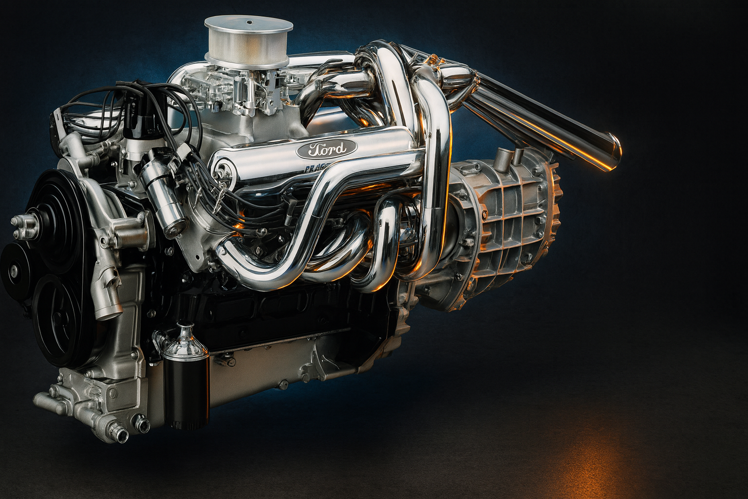
Ford builds a small block with race-bred canted valves and ports big enough to swallow a flashlight, then kills it after just a few years. If the 351 Cleveland was so good, why didn’t it keep going? Welcome back to Bono’s Garage. If you’ve ever stared down a Cleveland 4V intake port, you know it’s not your garden-variety small block. It’s a hallway: canted valves, massive cross-section, and a chamber design that was so far ahead of the gas you could buy at the pump it was crazy. So here’s the question again: if the 351 Cleveland was that good, why did it die a quiet death? Today we’ll tell the whole story, including the crazy head engineering, boiling issues, and how to build one that doesn’t suck. Then we’ll settle the Cleveland versus Windsor debate like grown-ups. By the end of this video you’ll know exactly how to spot a real 4V head, why quench is more than a buzzword, and how the Cleveland small block made big-block power through airflow and physics. From conception to early death, and from American muscle to Aussie street heroes, this is everything that made the 351 Cleveland the most misunderstood Ford small block ever built. This is your 351 Cleveland masterclass.
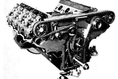
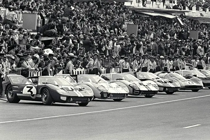
Look back at the late ’60s and Ford was all in on racing. They’d just blown the doors off Le Mans with the 427 side-oiler in ’66. Between NASCAR and Trans Am, Ford’s engineers had learned one thing: airflow wins races. The faster you could spin it, the more power you made, but that only worked if your heads could move enough air to keep up. At the same time, the Windsor plant in Canada couldn’t keep up with small-block demand, so Ford’s engine engineers in Cleveland, Ohio were told to build their own version. The mission was simple: build a small block that could take a deep breath at high RPM, then drop it into street cars and let the image sell the hardware. Racing credibility sold cars. If the same basic engine powered Boss Mustangs and stock cars, it wouldn’t just win trophies, it would win showroom traffic.
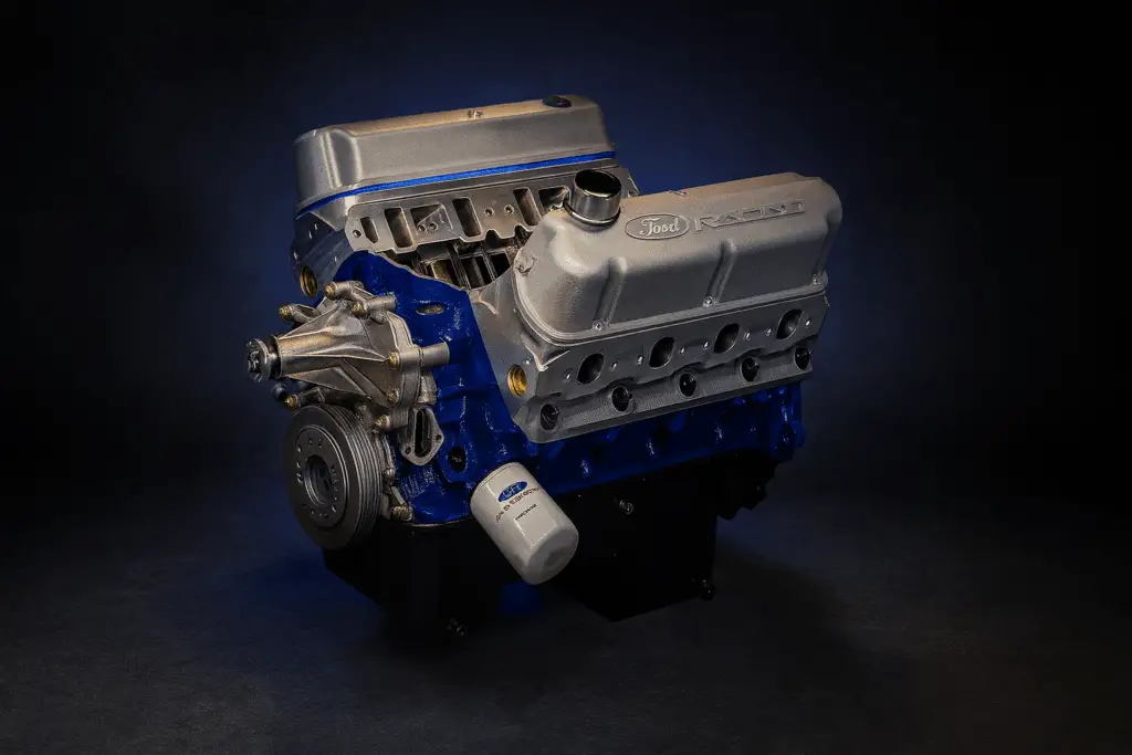
Enter the 351 Cleveland. What came out wasn’t just a copy; it was a whole new take on how a small block could breathe. It was a small block by Ford standards but used big-block thinking up top. The heads were a clean-sheet design, and on paper it looked incredible: massive ports, canted valves similar to the 429 and 460, and big valve sizes that let it breathe like an engine almost twice its size. It sat next to the Windsor on the showroom floor. The Cleveland was the hot ticket for a couple of shining years—Boss 351s, Panteras, Torinos—all running a small block that could hang with the best from GM and Mopar. It had the swagger, it had the numbers, and for a while it had the spotlight.
North American production kicked off in 1970 and wound down after 1974. That is quick. In that window the lineup included the 351C 2V for street torque, the 351C 4V for high-RPM heroics, the one-year Boss 351 in ’71 that showed what the architecture could do, and later Cobra Jet variants when emissions and lower compression started kneecapping the party. The 351 Cleveland was the first member of what Ford called the 335 engine family. The name came from management’s insistence that the engine be greater than 335 cubic inches, and it stuck as the project name. The family shared a lot of design DNA: wide pan rails, canted-valve heads, and castings meant to be modular across cars and trucks.
Something that could scale from a high-revving 351 for Mustangs and Torinos to a torquey 400 for full-size cars and pickups. I’ll save the M-block and 400 story for another video, but remember: the Cleveland wasn’t a one-off. It was the starting point for a whole generation of Ford V8s built around airflow, strength, and modular casting. So why did it fade so quickly? A few reasons stacked up, and if you’ve seen my other videos about engines from this era, the main chorus is the same: emissions rules turned brutal and compression came down. Those massive 4V ports needed a cam, aggressive gear ratios, and a high-flow carb to shine — things that became harder and harder to justify. Insurance companies didn’t help; they started hammering high-compression, high-horsepower cars with premium hikes so steep that buyers were paying more to insure a car than to own it. Anything with a big cam or high compression got labeled high risk, and Ford’s performance engines were in the crosshairs. Profit-wise, Ford already had tooling, supply chains, and a massive aftermarket built around the Windsor block. The Windsor plant in Ontario had been cranking out small blocks since the early ’60s; it had huge production capacity, established supply lines, and many livelihoods tied to keeping those machines running. The Cleveland plant, by contrast, was newer, smaller, and building an engine that didn’t share many components with the rest of Ford’s lineup. So when the early ’70s hit with tighter emissions, pricier fuel, and punitive insurance, it wasn’t even a close boardroom call. The Cleveland wasn’t killed because it was bad — it was killed because the world around it changed, and the Windsor fit that world better. Australia didn’t face the same tug-of-war. They had already invested heavily in Cleveland tooling for the Falcon GTs and doubled down, continuing to develop the heads and refine the chambers year after year. To be clear, Ford stopped building the 351C in the U.S. after the 1974 model year, but the Cleveland engine plant itself kept going and was retooled for newer engines — everything from small V6s to more modern units — and stayed active for decades after the Cleveland V8 was gone. While Ford in the U.S. moved on to the 351M and 400 in the Windsor family, Australia initially imported complete 351Cs from the U.S., then stockpiled about 60,000 American cast blocks when Dearborn stopped production. Once those ran low, Ford Australia started casting their own Cleveland blocks at the Gong Foundry. That’s where the 302C and the Aussie 351 came from — the same basic Cleveland design, but smaller.
Ports and those closed-chamber heads everybody loves today. That tells you something important: the Cleveland wasn’t a dead end; it was a victim of timing and priorities here in the States. Normally in an engine video I would start by talking about the block, but what makes the Cleveland engine special are the heads. The Cleveland engine shipped with two different head configurations from the factory: 2V and 4V. The V doesn’t stand for valve, as you might think, but for Venturi, since they were meant to be paired with two-barrel or four-barrel carburetors. All Cleveland heads were two-valve heads. The primary difference was the breathing design. 4V heads were designed to breathe far more, with huge intake and exhaust ports. Before we get deep into ports and chambers, we need to speak the same language: two quick concepts, shrouding and quench. Shrouding is your straight-valve setup, like a Windsor or a traditional small block. When the valve opens and gets close to the cylinder wall, the air gets pinched off. That shrouding kills low- and mid-lift flow — the RPM range where street engines usually live. The canted valve arrangement is typical of Cleveland heads. The valve is tilted back and away from the wall, so as it opens it unshrouds itself. You get much more flow without needing a monster cam. Ford didn’t invent this for the Cleveland; they borrowed it from the 429 and 460 big blocks — it works there and it works here. Quench refers to a closed-chamber design. The flat pad is the quench pad. When the piston comes up, the gap between the piston and pad is really tight, about 0.035 to 0.040 inches. That squishes the mixture across the chamber, forcing the air and fuel to tumble and mix, which speeds up the burn and helps fight detonation because the charge burns fast and predictably instead of lazy and patchy. Compare that to an open chamber, where Ford basically milled out the whole section into a big bowl: no real squish or tumble and a lazier burn. That worked for emissions but not for throttle response or knock resistance. That’s why the early closed-chamber 4V heads are so desirable. In the U.S., every 2V head got the open chamber; only the early 4V heads had the good closed quench. But down in Australia, Ford kept the smaller 2V ports.
Street velocity, and they also kept the closed chamber. That’s why the Aussie heads are the hot street combo today: small ports, good velocity, and real quench. Now that we have those two ideas straight, let’s talk about the ports themselves. Cleveland 4V heads were absolutely unhinged for a production small block: huge intake runners, gigantic valves, with that canted layout and almost no shrouding at the gasket. The 4V intake port window is about 2.5 by 1.75 inches — that’s the size of a Motorola power brick. That brick-sized hole is feeding 2.19-inch intake and 1.71-inch exhaust valves — that’s the bottom of a spray can and the size of a challenge coin, respectively. That’s how Ford ended up with a small block that breathes like a big block. The 2V ports pull things back to reality: a much smaller window, more like a dog tag, but still with canted valves. Still good flow, just tuned for street velocity instead of 7,000 RPM dyno pulls. You lose some top-end bragging rights, but the engine wakes up much earlier in the RPM range, which on real roads actually matters more. All factory Cleveland heads were cast iron; there were no aluminum options from Ford. The early closed-quench 4V chambers measured around 61 to 63 cc, while the later open-chamber 4V and all 2V heads were closer to 74 to 77 cc. That change alone dropped compression almost a full point. Most early 4V engines ran roughly 10.7:1 compression, while later open-chamber versions were closer to 9:1 or even the high eights depending on piston dish and how far the piston sits in the bore from the factory. Back in the early ’70s that mattered because premium meant high-octane, leaded fuel. When unleaded and lower-octane blends took over, those high-compression closed-chamber combos became picky about spark advance and fuel quality. The open chambers were Ford’s answer: cheaper to build, burned cleaner, and tolerated the lousy pump gas of the era. Those two head designs gave the Cleveland a split personality depending on your head choice — brutal on the track with a 4V and high compression, or smooth and drivable on the street with a 2V and open chambers. To tell the difference between Cleveland heads, look at the intake face: 4V ports are rectangles big enough to lose a socket in, while 2Vs are shorter and more oval. If you can inspect more closely, verify by using casting numbers on the underside of an intake runner after the intake is off; the date code is also under the valve cover. Underneath the Cleveland block itself is a stout piece of iron with surprisingly good main webbing for a small block of its era. The deck height is 9.206 inches, putting it squarely in small-block territory. The rotating assembly geometry is well balanced for RPM. With a 4-inch bore and 3.5-inch stroke, the 351C carries a 1.65:1 rod ratio thanks to its 5.780-inch connecting rods, which helps it rev cleanly as long as the rest of the combo is built to let it breathe. The main journals measure 2.75 inches, smaller than the 3-inch mains used in later 351M and 400 engines, which means less bearing speed and less drag at high RPM. Crank journals are wide and strong.
Clevelands can handle 6,000-plus RPM without drama if the clearances and balances are right. A bare Cleveland block weighs about 190–210 lb, and a complete long block tips the scale near 525 to 575 lb depending on accessories and intake choice. That’s right in line with other Ford small blocks, but a little heavier than a Windsor thanks to beefier castings and heads. It uses the same firing order as the 351 Windsor. Where people really start arguing is the oiling path. You’ll hear folks say that the Cleveland feeds the top end first or that it starves the mains because of how the galleries are laid out, and that’s close to the truth but not the whole picture. The oil pump sends pressure straight up the front of the block right next to the number-one main and cam bearings, and a diagram can make it look like those bearings should get oil first. Hydraulically, though, oil takes the path of least resistance, and in a Cleveland that path is the big right-side lifter gallery. It’s a long, wide passage that feeds all eight right-side lifters and several cam bearings, so oil rushes down that gallery before it commits to dropping into the mains. Once the galleries fill and the system builds pressure, the mains then start getting their share, so the number-one bearing isn’t dry—it’s just not first in priority. At low RPM none of this is a big deal because there’s plenty of pressure to go around, but when you spin a Cleveland hard those big lifter bores and generous passages become a large leak path. The top end can dump more oil than the pump can replace, and since the mains are last in the hydraulic order they’re the ones that pay the price. That’s why serious builders talk about lifter bushings, gallery restrictors, and matching the right pump to the build. Bushings and restrictors tighten the leak paths, and a high-volume pump keeps pressure where the crank needs it. Do that, and a Cleveland will run north of 6,000 rpm all day long without losing a bearing. A fun bit of Ford trivia: the Cleveland’s oiling reputation gets compared to the old FE engines, especially the early center-oilers. Those FEs fed the crank last, which is why Ford introduced the famous side-oiler. The Cleveland isn’t the same situation, but the symptoms are similar. Why didn’t they give the Cleveland the same fix? Timing, priorities, and cost. Ford was designing a high-volume street motor that needed to meet emissions and cost targets, not a race engine. At normal street RPM that’s no problem; the issue only shows up when you spin it hard for long stretches, exactly what racers love to do, and racers then hot-rodded the valve system. One more thing to note if you’re building one: most production Clevelands run a non-adjustable valve train. That means stamped rockers on cast pedestals, the same setup Ford used on their big 429 and 460 engines. The hydraulic lifters take up the slack automatically, so there’s no lash to set with a wrench. If you need more or less preload, you change the pushrod length.
Shim the fulp. The Boss 351 and later 351 HO were the exceptions. They got screw-in studs, guide plates, and solid lifters, which meant a fully adjustable setup built for real RPM. That’s one of the reasons those two are the ones everybody still talks about. The name of the game with this engine is airflow. Induction strategy is where you make or break a Cleveland. A 4V with a tiny cam and a lazy dual-plane intake can feel like a tractor that lost its wallet until about 3,000 RPM. That’s not the engine’s fault; that’s mismatched parts. The 4V’s massive, 250-ish cc intake runners move a ton of air up front, but they need velocity to work down low. Give it some cam duration, decent lift, and an intake that actually feeds those ports. Then back it up with real gear and converter, and suddenly the lazy disappears. You get exactly what Ford intended: the top-end freight train. On the 2V, you can lean toward a shorter cam, keep the dual plane, and enjoy crisp throttle and street torque. The smaller 190-to-210 cc ports build velocity fast, which means better low-end pull and clear mixture motion through the midrange. Carb sizing matters. Don’t strangle it, but don’t slap on a barn door either. A well-calibrated 650 to 750 CFM carb is perfect for most 351C street builds, while a hotter 4V combo loves 750 to 850 CFM when the RPM is there. If you go EFI, the giant-port personality of the 4V gets a little friendlier at low speed. Modern fuel control and injector timing help fill in that off-idle hole and make the Cleveland behave like a high-tech small block it always kind of wanted to be. There are a lot of terms around, so let’s narrow in on variance for a moment because the term Cleveland covered a few different animals. I’ve already gone over the head versions, but it’s worth looking again in relation to where they all ended up within the larger Cleveland line. To start with, here’s how the codes break down. The H code was the 2V street engine. The M code was the hot, closed-chamber 4V. The R code was a solid-lifter Boss. The later Q code was the tamed-down Cobra Jet with open chambers for emissions. The letters changed, but the heart of the Cleveland stayed the same. Down in Australia, things got interesting. The Aussie 302 C and 51C heads blended the best traits: two V-sized ports for velocity with closed quench chambers for detonation resistance. That combo made a lot of street builds feel stronger than the spec sheet would suggest. They’re the full caro of Cleveland swaps for a reason. You’ll find Clevelands in Mustangs, Torinos, and even the Tomaso Penta where that high-flow 4V really showed off. Across the Pacific, Australian Falcons were out there turning the same architecture into Brathurst racing legend. Here’s a list compiled from known factory data and enthusiast sources. Local options or export versions may differ. Before we move on, a quick name trap: the 351M and 400 are part of the same 335 engine family, but they’re not true Clevelands. They use a taller deck, larger mains, and a different bell-housing pattern. Some parts interchange, but if you call a 351M a Cleveland, be ready for an internet jockey to call you a noob. Let’s talk about what usually trips people up with these engines and what actually fixes it. First up: oiling and RPM. I’ve said before, the Cleveland’s oil system can starve the mains if you spin it hard with loose clearances or worn
The fix depends on how wild your build is. For serious engines, lifter bore bushings keep oil where it belongs. You can also add restrictors to the lifter galleries to slow down the flow upstairs. As always, match your oil pump to the combo. A high-volume pump is great when the system is set up for it, but it’s just a band-aid if you’re masking wear or bad geometry. Cleveland cooling is different. It wants the correct Cleveland-style thermostat or a restrictor plate. There’s a bypass passage built into the housing that needs to be managed so the engine reaches temperature and circulates correctly. The proper thermostat has a little hat or sleeve that closes the bypass once it’s warm. If you’re on a Windsor-style thermostat, that bypass stays open and you’ll have weird warm-ups, hot spots in the heads, and an engine that always seems too warm no matter what you do. These blocks and heads have been around for 50 years or more. You’ll see core shift, valve guide wear, and the occasional mystery machine work from a previous rebuild. If you’re planning a major rebuild, get the block sonic checked before you spend money on parts. On the heads, check valve guides and seats carefully. Detonation on open-chamber heads is a real concern. With modern pump gas, you can’t get away with the same compression and timing those engines ran on leaded premium. Open-chamber 4V heads especially can rattle if you push them too hard. If you’re chasing power, a modern aftermarket head with a tighter heart-shaped chamber is a smart upgrade. More on that later. There are a few different ways you can build up a Cleveland depending on how wild you want to get: street, street/strip, or all-out track. Each combo changes cam specs, compression, and gearing. If you want the full recipe list — everything down to lift numbers and header sizes — I have it all laid out on bonelessg.com. The link is in the description. At the factory, Cleveland was ahead of its time. The aftermarket finally caught up. Fifty years later, the parts catalog for this thing is wild. You can build a Cleveland from bare iron to high-power setups, except maybe the block itself. Today’s aluminum Cleveland heads are basically a cheat code: you get 4V-level top-end airflow with smaller, faster ports that don’t go to sleep at 2,000 rpm. Companies like Trick Flow, CHI, and Edelbrock have the formula nailed. They feature modern heart-shaped quench-style chambers that let you run real compression on pump gas without detonation. Pair that with a dual-plane intake that matches the port cross-section you actually have, and you suddenly have a Cleveland that acts civilized in traffic and wicked at wide-open throttle. The oiling fixes are old news now, dialed in and improved: lifter bore bushings in serious builds, gallery restrictors to keep pressure where it belongs, and high-volume pumps that actually match the clearances you set up. Run a real oil pan — seven or eight quarts — with proper baffling, and use a pickup that’s welded or safety-wired so it doesn’t vibrate off and ruin your weekend. Here’s a bit of free advice: don’t oversize the exhaust just because it’s a Cleveland. Small tubes make torque. 2V heads love 1-5/8 to 1-3/4 inch headers. High-rpm 4V combos can use 1-3/4 to 1-7/8 inch. On the street, bigger isn’t always faster; sometimes it’s just louder. Finally, something to note is that EFI conversions…
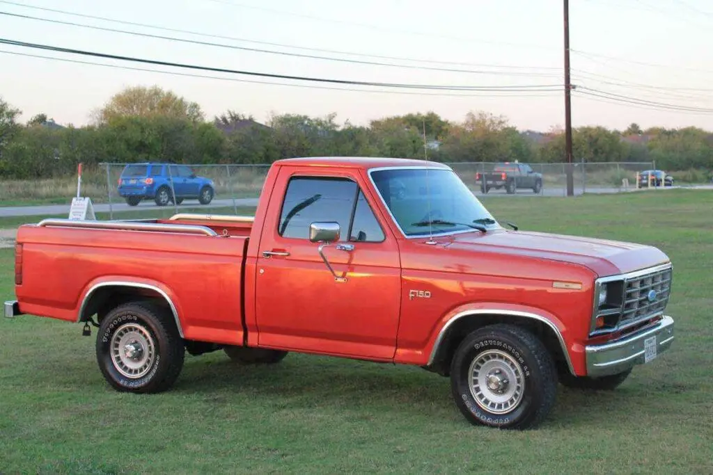
The giant 4V ports that struggled with fuel distribution in the ’70s suddenly make sense when you can meter fuel per cylinder. Throttle-body EFI helps, but multiport is where the manners really sharpen up — cold starts and part-throttle response. It’s like the Cleveland finally learned some table manners. Shop-floor showdown: Cleveland or Windsor? It’s an argument that’s echoed through garages for 50 years. Full disclosure: I’m a Windsor man myself, but bias aside, here’s the honest truth. The Windsor wins on practicality. Parts are cheaper and easier to find, and there’s a stroker kit for every budget. It’s lighter in many trims, the oiling system is simpler, and if you want plug-and-play street torque with everything on the shelf at Summit or your local parts store, the Windsor is a layup. It just works. The Cleveland, though, is pure Ford magic. Even in stock trim, nothing else in the small-block Ford world moves air like it. Those heads flow like race parts right out of the gate. The valvetrain stays stable at high RPM and the top end just keeps pulling when a Windsor would have already gone home. If you love an engine that wakes up hard from the midrange and keeps pulling long after a Windsor is tapped out, the Cleveland speaks your language. And yes, you can put a Cleveland in one of our trucks. If your rig had a 351M or 400, it’s a bolt-in deal — same family, same mounts. In an F-150 or Bronco that came with a Windsor or an inline-six, it’s more of a project: you need a rear-sump pan, custom mounts, and probably a Saturday or two of bracket bingo. But once it’s in, you have one of the coolest Ford mashups out there. When should you pick which? If your goal is around 400 treatable horsepower with good manners and minimal drama, the Windsor is easy mode: bolt it together, tune it, and enjoy it. But if you want a street-strip setup that feels like a small block pretending to be a big block, or you want the coolest Ford conversation piece in the parking lot, the Cleveland is your answer — especially if you’re running Aussie-style quench heads or a modern aluminum casting that brings the ports back to street velocity. Honestly, if my current build weren’t my first serious attempt at a truly streetable high-horsepower combo, the Cleveland would be awfully tempting. Someday I’d love to build a Cleveland just to remind myself why some Ford engineers in Ohio thought this crazy thing was the future. When De Tomaso dropped a Cleveland in the mid-engine Pantera, suddenly this blue-collar Ford engine was sharing poster space with Ferraris. It gave the 351C race-bred heads, an exotic sound, and European sheet metal. That combo made the legend stick — the Pantera made the Cleveland feel exotic. Those canted valve heads also changed how people thought about airflow and combustion. They taught a whole generation to respect chambers, velocity, and mixture motion. Quench stopped being a buzzword and became a philosophy. That’s why people still hunt for those two V-port quench chamber combos for street builds, and why the words Boss 351 still make people straighten up at car shows. The Cleveland didn’t lose because it was bad — it lost to its own era, emissions, and corporate politics.
Cleveland disappeared. But was it so good it got cancelled? Not exactly. Its timing clashed with emissions, fuel, insurance, and corporate priorities, even though the design itself was excellent. The heads were revolutionary and the block was clever. With the right parts it is still an absolute riot. But the early ’70s weren’t kind to any engine, let alone engines that needed compression, cam, and clean fuel. The Windsor survived in the industry because it was simple and scalable. The Cleveland lives in our hearts because it was special. And that’s everything I know or pretend to know about the Ford 351 Cleveland engine.
Have one, want one, or think I should dump my Windsor for a Cleveland instead? Think I should forget getting some aftermarket Windsor heads and build up a Cleveland instead? Drop me a line. If you have any other questions, comments, concerns, or gripes, drop them below.
If you want to dig deeper into the builds, the side projects, and the stuff that doesn’t always make it on YouTube, or just want to get to know me better, come hang out on patreon.com/bullnose Garage. It helps keep the lights on, and I appreciate you being part of the garage. Thanks again for watching — we’ll see you next time.
Ford built a small block with canted valves and intake ports big enough to lose a socket in, then killed it after a few short years. If that sentence makes you tilt your head, you’re exactly who this video is for.
In this 351 Cleveland masterclass, I walk through what made the Cleveland special, what doomed it in the U.S., and how to build one today that doesn’t suck. We hit 2V vs 4V, quench vs open chambers, the real oiling path, Aussie heads, modern parts, and whether you should pick a Cleveland or a Windsor for your project.
Why Ford Built It—and Why It Disappeared
Late ’60s Ford was drunk on airflow and racing. NASCAR and Trans Am taught a simple lesson: heads win races. The Windsor plant couldn’t keep up with demand, so the Cleveland, Ohio team was told to build their own small block with big-block thinking up top. Enter the 351 Cleveland in 1970.
In just a few years we got the 351C 2V (street torque), the 351C 4V (high-RPM hero), the one-year Boss 351 (’71, the full send), and later Cobra Jet variants as emissions rules dragged compression down. North American production wound down after 1974. Not because the Cleveland was bad, but because the early ’70s were. Emissions got brutal, compression dropped, insurance punished power, fuel quality slid, and Ford already had the Windsor on a massive, cost-effective production base.
Australia didn’t flinch. They invested, stockpiled roughly 60,000 U.S. blocks when Dearborn stopped, and then cast their own at the Gong Foundry, giving us the 302C and Aussie 351. Same architecture, smarter chambers for the street. The Cleveland wasn’t a dead end; it was a victim of timing and priorities here in the States.
The Heads That Made the Legend
2V vs 4V: Venturi, Not Valves
“V” stands for Venturi, not valve count. All Cleveland heads have two valves per cylinder. The difference is breathing. The 4V heads are wild: huge ports and big valves for high-RPM airflow. The 2V heads are smaller, designed for port velocity and street manners.
Shrouding vs Canted Valve Unshrouding
Traditional straight valve layouts get shrouded by the cylinder wall at low lift. The Cleveland’s canted valves tilt away from the wall and unshroud as they open. Result: more flow without needing a ridiculous cam. Ford learned it on the 429/460 big blocks, then shrunk the concept into a “small” block.
Quench vs Open Chamber
Closed-chamber (quench) designs use a tight pad—about 0.035–0.040 inch piston-to-head—to squish the mixture, boost turbulence, and speed the burn. That helps power and fights detonation. Open chambers are, well, open: easier emissions, lazier burn. In the U.S., all 2Vs were open-chamber. Early 4V heads got the good closed-chamber quench, which is why they’re coveted.
Australia kept the smaller 2V-style ports and paired them with closed chambers. That combo—velocity plus real quench—is why “Aussie heads” are the hot street setup today.
Port Size, Chambers, and How to Spot the Real Stuff
4V port window: roughly 2.5 x 1.75 inches—“power brick” territory.
Valve sizes: 4V uses about 2.19-inch intake and 1.71-inch exhaust.
2V port window: much smaller, more oval—dog-tag sized compared to 4V.
Chamber volumes: early closed-chamber 4V ~61–63 cc; later open-chamber 4V and all 2V ~74–77 cc.
Compression: early 4V combos around 10.7:1; later open-chamber builds often near 9:1 or high 8s depending on pistons/deck.
How to ID them: look at the intake face. If the port looks big enough to swallow a flashlight, it’s 4V. Smaller, oval-ish ports are 2V. Casting numbers live under an intake runner (intake off) and date codes are under the valve cover.
The Block, Geometry, and What It Weighs
The 351C bottom end is stout for its era: strong main webbing and smart dimensions that like RPM when the combo is matched.
Key Specs
Bore x stroke: 4.000 x 3.500 inches
Rod length: 5.780 inches; rod ratio ~1.65:1
Deck height: 9.206 inches
Main journal: 2.75 inches (smaller than 351M/400’s 3.000, so less bearing speed)
Weight: bare block ~190–210 lb; complete long block ~525–575 lb (accessories/intake dependent)
Firing order: same as 351W
Translation: a Cleveland will happily spin past 6,000 RPM with the right clearances and balance—and with oil control handled (more on that next).
Oiling Reality—and Real Fixes
The Gallery Path, Explained
The myth says “it feeds the top end first.” The truth: hydraulically, the right-side lifter gallery is the path of least resistance. Oil rushes there before it fully settles into the mains, especially at higher RPM. Once pressure builds, everyone gets served but at sustained RPM, those big lifter bores and generous passages can become a leak path. The mains are last in line and can suffer if you ignore the combo.
Fix What Matters
Lifter bore bushings: tighten leak paths on serious builds.
Oil gallery restrictors: slow the upstairs flow so the crank keeps pressure.
Right pump, matched to clearances: a high-volume pump helps when the system is prepped; it’s not a band-aid for worn geometry.
Real pan and pickup: 7–8 quarts, baffled. Secure the pickup (weld or safety-wire) so it doesn’t vibrate off and ruin your weekend.
Handled properly, a Cleveland will live north of 6,000 RPM all day without eating bearings.
Cooling Quirks You Can’t Ignore
Cleveland cooling needs the correct Cleveland-style thermostat (or a restrictor plate). The housing has a bypass passage that must be controlled. The proper thermostat has a sleeve/“hat” that closes the bypass once warm. Run a Windsor-style stat and the bypass stays open… hello odd warmups, hot spots, and a motor that always runs warmer than it should.
Valvetrain Notes
Most production 351Cs use a non-adjustable valvetrain: stamped rockers on pedestals with hydraulic lifters. Preload is handled by pushrod length, not lash nuts. Exceptions: Boss 351 and later 351 HO got screw-in studs, guide plates, and solid lifters. Fully adjustable and happy at real RPM.
Building a Cleveland That Doesn’t Suck
Induction and Cam Strategy
The name of the game is airflow… matched, not mismatched. A 4V with tiny cam and a lazy dual-plane feels like a tractor that lost its wallet until ~3,000 RPM. Give it duration, real lift, and an intake that actually feeds those giant ports, then back it with gear/converter. The freight train shows up.
On a 2V, lean into velocity. Shorter cam, dual-plane intake, and enjoy street torque and crisp throttle. Smaller ports (roughly 190–210 cc) build velocity early and keep mixture motion through the midrange.
Carb vs EFI
Carb sizing: 650–750 CFM works for most street 351Cs; a hotter 4V build with real RPM likes 750–850 CFM.
EFI: the big 4V ports get friendlier at low speed with modern fuel control. Throttle-body helps; multiport makes it behave—cold starts, part throttle, cylinder-to-cylinder fuel.
Headers That Help (Not Hurt)
2V street: 1-5/8 to 1-3/4 inch primaries.
High-RPM 4V: 1-3/4 to 1-7/8 inch.
Don’t oversize just because “Cleveland.” Smaller tubes build torque; bigger is often just louder.
Variants, Codes, and Aussie Gold
H-code: 2V street engines.
M-code: hot, closed-chamber 4V.
R-code: Boss 351, solid lifter, adjustable valvetrain.
Q-code: later Cobra Jet with open chambers (emissions-era tame).
Australia blended the best traits: 2V-sized ports for velocity with closed quench chambers for detonation resistance. That’s why Aussie heads are coveted for street builds. And yes, the same Cleveland architecture powered everything from Boss Mustangs and Torinos to the De Tomaso Pantera—where the 4V really showed off. Over in Australia, Falcons turned the platform into Bathurst legend.
Name trap while we’re here: 351M and 400 are part of the 335 family but aren’t “true” Clevelands. Taller deck, bigger mains, different bellhousing pattern. Some parts interchange—just don’t call a 351M a Cleveland unless you like comment wars.
Cleveland vs Windsor—Like Grown-Ups
Full disclosure: I’m a Windsor man myself. Bias aside, here’s the honest take.
Windsor: wins on practicality. Lighter in many trims, simpler oiling, cheaper parts, a stroker kit for every budget, and shelves of bolt-on street torque.
Cleveland: pure Ford magic. Nothing else in the small-block Ford world moves air like a Cleveland’s heads. Stable valvetrain, top end that keeps pulling when a Windsor is clocking out. With the right combo (and especially modern heads), it’s a small block that pretends to be a big block.
Swapping a Cleveland into a Bullnose
If your truck had a 351M or 400, this is about as bolt-in as it gets—same 335 family, same mounts. For F-150s or Broncos that came with a Windsor or inline-six, plan on a rear-sump pan, custom mounts, and a Saturday or two of bracket bingo. Once it’s in, you’ve got one of the cooler Ford mashups out there.
Aftermarket Heads and Modern Fixes
The aftermarket finally caught up with the Cleveland. Today’s aluminum heads (Trick Flow, CHI, Edelbrock) are basically a cheat code: 4V-level airflow with smaller, faster ports that don’t go to sleep at 2,000 RPM. They use modern, heart-shaped quench chambers so you can run real compression on pump gas without detonation. Match the intake to the actual port, not the one in your imagination, and you get street manners plus top-end pull.
Oil system fixes are well known by now: lifter bore bushings on serious builds, sensible restrictors, and a high-volume pump when clearances justify it. Run a baffled 7–8 qt pan and secure that pickup. Do the Cleveland thermostat correctly and you won’t be chasing phantom heat.
What to Inspect Before You Spend
Block: sonic check old castings for core shift before you buy pistons.
Heads: guides and seats—decades of wear and “mystery machine work” show up here.
Detonation risk: open-chamber 4V heads can rattle on modern pump gas if you chase timing/compression too hard. Tighter modern chambers fix a lot of that.
So, Which One Should You Build?
If you want ~400 honest, streetable horsepower with minimal drama, the Windsor is easy mode. If you want a street/strip setup that hits like a freight train from the midrange up—and you want the best Ford parking-lot conversation starter—the Cleveland is your engine, especially with Aussie-style quench heads or modern aluminum castings that bring port velocity back.
Someday I’d love to build a Cleveland just to remind myself why Ford’s Ohio team thought this was the future. The era killed it—not the engineering.
Wrap-Up
The 351 Cleveland was short-lived in America but far from a footnote. Revolutionary heads, a clever block, and with the right parts it’s still an absolute riot. If you want the full combo recipes—cams, header sizing, and more—I’ve laid them out on bullnosegarage.com. Check out the video above for the full walkthrough.
Got a Cleveland story, an Aussie head score, or a Windsor vs Cleveland hot take? Drop it in the comments. I read them all, even the ones that tell me I’m wrong.
If you want more specific information on Bullnose Ford Trucks, check out my YouTube Channel!
As an Amazon Associate, I earn from qualifying purchases. If you see an Amazon link on my site, purchasing the item from Amazon using that link helps out the Channel.
If you’re anything like me, you have all kinds of stuff in your garage and basically know where to put it. I should pan around the garage and show you what a mess it is most of the time. It’s not because I’m a messy guy; it’s because I have so much stuff and so little space. That’s a common garage issue. I’m always looking for ways to make storage make sense. One of the things I recently did was teach myself how to weld. I’m not an expert yet, but I can at least stick two pieces of metal together with fire, which is cool. I built a welding table and I’m pretty happy with it. It works really well. If you work with metal, you need a bunch of tools: a vise, a grinder, flap discs, an angle grinder, a welder, and all the accessories. To simplify storage, I built a quick interchange system using 2-inch hitch receivers. I want to show it to you because you might want to use it too. So, take a look. [Music] Howdy folks, Ed here. Welcome back to Bono’s Garage. This is my 2-inch hitch receiver mount system. You can see one here, another on the wall for storage, and this one is an old truck rim, a driveshaft, and a 2-inch rotating hitch receiver that lets me mount my grinder or vise in any of these positions. It’s super simple. I use 2-inch receiver mounts with a rotating head. You can pull a pin and rotate the head. They were only about $20 more than a regular mount and give much more flexibility. With a vise it’s not necessary since the vise itself can rotate, but it adds another axis for extension. It’s simple: you slide it in, pin it, and screw it down so it doesn’t move. Now I have a vise that can move around the shop. This is handy because I can take the tools outside to grind metal without filling the garage with metal shards that stick to every magnet. I can work in the driveway, keeping the garage clean. I can also mount the grinder. These setups are heavy, but they work.
There we go. If I want to grind some metal outside, I can do that with this too. I put this little foot on the bottom to keep it from rocking forward, and it works pretty well. I’m never going to be able to wrench on a 10-foot pole with this, but that’s not what it’s designed for. It’s designed for me to take stuff outside and grind on it out there, keeping it out of the way of the garage. When I’m ready to work inside on a more stable platform, I can take this off, bring it over to my bench, slide it in, and plug it in. Now I can grind here. If I need to use my vise instead, I slot that in and store it on the wall. I have these screws on here to keep it from moving, which makes it hard to install if I don’t undo them. There we go. Now my vise is ready to use. It’s pretty stable, though it flops a bit. I have some screws in the hitch receiver I can use to lock it down better. This is never going to be as stable as a full bench-mounted vise, but for what I’m doing here, it’s perfect. And now for the really cool part. Howdy, folks. It’s your slightly desperate channel support reminder. You can keep Bono’s Garage running strong by joining the crew on Patreon or picking up some merch at bonar.com. I promise every single penny goes straight into parts and channel upgrades. I buy my own beer. This 2-inch hitch receiver sits on the end of a steel pipe that runs underneath the table through two pillow blocks, so it can rotate up and down. I’m using DJ light bar braces—the kind used to hang DJ lights from a truss system mounted under a table—to keep the steel pipe from rolling up and down, and it works. If I loosen this, I’m going to take the vise out because I don’t want it dropping down on me; that would be really embarrassing. It’s held down with wing nuts, so I use my wing nut wrench to loosen them. This isn’t meant to be adjusted all the time because I won’t use it like this often, but when I want to, I can rotate it up and mount it straight up and down or out here if I need to. If I had to come at something from underneath or needed a different angle, no problem. I’m holding it because if I don’t, it’ll flop down since I haven’t tightened the braces. The whole thing will go up and down, and all I have to do is tighten it down there to keep it from moving. I’m not sure I can do this hand-tight enough to keep it from moving on camera. Let’s see—oh.
Hand-tight is enough to keep it from moving so I can show you. That’s how it works. I couldn’t wrench on this in any major way because it would move on me, but there we go—it’s moving because I had to tighten it down. That’s what I have the wrench for. It’s a short video this week. I wanted to show this system I put together because I think it’s pretty cool. If you wanted to use something like this in your shop, you could: put as many hitch receivers on the wall as you have room for and hang as many tools as you want. I’m thinking about getting a smaller drill press to put on here, one of the magnetic ones. There are a couple other tools that might work on a platform like this. If I wanted to, I could take this out and put it in the back of my truck, right on the hitch of my newer Ford. Will I ever do that? Who knows. But now I can, and that’s half the fun of garage projects—you make things so you can use them that way, even if you never do. The link to all of the stuff I used to make this happen is in the description. Some of it’s kind of expensive, but not terrible, and it should last a long time. Now I have a great way to move projects for welding, grinding, cutting, or any metal work in and out of the garage to make the workflow more efficient. That’s it for now. Thanks so much for watching. If you have questions, comments, concerns, or suggestions—if you want to know more about how I did this or have done something similar—drop them below. I really appreciate it. We’ll see you next time. It’s following me around—can you stop? If you want to dig deeper into the builds, the side projects, and the stuff that doesn’t always make it on YouTube, or just want to get to know me better, come hang out on patreon.com/bullnose Garage. It helps keep the lights on, the beer fridge full, and the builds funded. Appreciate you being part of the garage. Thanks again for watching; we’ll see you next time.
If your garage is bursting at the seams with tools and “stuff I might need someday,” welcome to the club. I got tired of playing floor-plan Tetris every time I wanted to grind, weld, or clamp something. So I tried something a little ridiculous that turned out to be… not ridiculous at all.
Short version: I built a portable vise and grinder setup around 2-inch trailer hitch receivers. Now I can mount a tool on the wall, at the welding table, or on a freestanding base, and move it outside when I don’t feel like sandblasting the shop with metal dust. It’s simple, stout, and way more flexible than I expected.
The 2-Inch Hitch Receiver Mount System
The heart of this setup is a set of 2-inch hitch receivers and interchangeable tool mounts. I’ve got three main locations:
A receiver on my welding table
A receiver on the wall (for storage and quick swaps)
A freestanding mount made from an old truck rim and a driveshaft
For the tool-side mounts, I used 2-inch receiver pieces with a rotating head. They cost about $20 more than a standard fixed mount, but the extra axis is worth it—especially for the grinder. With a vise, it’s not strictly necessary because most vises rotate on their own, but the added articulation makes positioning easier. It’s a slide-pin-tighten operation: drop the mount in, pin it, snug the screws so it doesn’t wiggle, and you’re in business.
Why Hitch Receivers Work in a Small Shop
Hitch receivers are built to locate and secure heavy things quickly. Turns out they’re perfect for tools, too. The big wins here:
Interchangeable tools: Swap a grinder for a vise in seconds without dedicating a chunk of bench space to either one.
Mobile dust control: I can drag the grinder mount outside and keep the garage from looking like a glitter bomb hit a magnet factory.
Modular storage: The wall receiver doubles as a parking spot when a tool isn’t in use.
Flexible angles: The rotating head and the table-mounted rotating pipe (more on that in a second) make awkward workholding less awkward.
The Components (and Why They Matter)
Rotating Receiver Mounts
These are just standard 2-inch hitch receiver mounts with a rotating head. Pull a pin, change the angle, drop the pin back in. They add another axis of alignment so you can bring the work to you instead of contorting around the tool. For grinding and light fab work, they’re ideal.
Vise and Grinder, One System
The vise and the grinder each live on their own hitch insert. When I want to grind outside, the grinder goes on the freestanding base. When I need to clamp and beat on something, the vise moves to the welding table. When one’s in use, the other can hang out in the wall receiver. Easy.
Locking It Down
Receivers are solid, but tools still need to be tightened. I’ve got screws on the mounts to snug them in the receiver and keep the play down. That also means if I forget to back those screws off, the swap can be a bear. Ask me how I know. The message here: snug for stability; loosen before you yank on it.
The Freestanding Rim-and-Driveshaft Stand
This is the portable workhorse: an old truck rim for the base, a driveshaft for the upright, and a 2-inch rotating receiver on top. It’s heavy (which is good), it rolls enough to move around (also good), and it has a small foot at the bottom to keep it from pitching forward under load (very good). I’m not trying to pull on a 10-foot cheater bar with this thing—because that’s not what it’s for. It’s for taking the grinder (or a vise) outside, doing the dirty work there, and bringing it back in without dragging half the driveway in with it.
Stability-wise, it’s plenty for normal grinding, fitting, and light clamping. If you’re expecting bench-vise rigidity on a freestanding stand, you’re going to be disappointed. But for the intended use, it’s right on the money.
The Wall Receiver
The wall receiver is the simplest piece, and it earns its keep. It stores whatever tool isn’t in use and doubles as a quick-use station when I just need to make a fast touch-up. Receivers aren’t just for trucks—they make solid wall mounts too.
The Welding Table: Rotating Pipe Mount
Here’s where it gets fun. The receiver at the end of my welding table is welded to a steel pipe that runs underneath the table through two pillow block bearings. That pipe can rotate, which means the whole receiver can swing up, down, or anywhere in between. I’m using DJ-style truss clamps (the light bar braces used to hang stage lights) under the table to lock the pipe in position. They’re hand-friendly with wing nuts, and I keep a wing nut wrench nearby to give them an extra snug when I need it.
Use case: if I need the vise vertical, horizontal, or somewhere off the edge of the table to get under a part, I can swing the receiver to where I want it and clamp it in place. Hand-tight can hold for light duty; for anything more convincing, a quick hit with the wing nut wrench locks it down nicely.
Could I reef on this setup like a fixed bench vise? No. It’ll move before the steel does. But for positioning, odd angles, and making the most of limited table space, it’s a killer option.
What It Can (and Can’t) Do
Can: Let me mount a vise or grinder in multiple places, change orientations fast, and move the mess outside.
Can: Keep the shop cleaner by doing grinding in the driveway so the magnetic gremlins don’t collect every tiny metal shaving.
Can: Save space by using one set of mounts for multiple tools.
Can’t: Replace a bolted-to-the-floor industrial vise for high-torque work. It’s not designed for that, and I’m not pretending it is.
Future Add-Ons I’m Considering
I’m eyeing a smaller magnetic-base drill press to drop into a hitch insert. A couple other tools would adapt nicely to a platform like this, too. And yes, I could stick one of these mounts right into the hitch on my newer Ford and have a field vise in the driveway or on a job site. Will I? Maybe. The point is, I can—and that’s half the fun.
Build Notes and Tips
Receiver choice: The rotating head mounts cost a bit more than fixed mounts, but the flexibility pays off immediately—especially on the grinder.
Snug matters: Set screws or clamp screws in the receiver make a big difference in how “solid” the tool feels.
Balance your freestanding base: A wide base (like a truck rim) plus a small anti-tip foot keeps things composed when you’re leaning on the work.
Use the right clamps under the table: Pillow block bearings let the pipe rotate smoothly, and truss clamps with wing nuts make locking it down fast and tool-free most of the time.
Know the limits: This is not a dragline anchor. It’s a smart way to reconfigure common tools and move work zones around without rebuilding the shop.
Because it’s simple. Hitch receivers are an existing, standardized interface with great mechanical engagement and fast changes built in. Add a rotating head, give yourself a few places to plug in around the shop, and suddenly the same tools have three lives: on the wall, on the table, or out in the driveway. When space is tight and your tool list is long, modular beats permanent every time.
Wrap-Up
That’s the whole setup: receivers on the table and wall, a freestanding rim-and-driveshaft stand, a rotating pipe with pillow blocks, and a couple of tools on hitch inserts I can swap in seconds. It’s not fancy, but it’s absolutely effective—and my garage is a lot less sparkly because of it.
Want to see it in action? Check out the video and let me know what you’d add to the system, or how you’d tweak it for your space. Questions, ideas, or better ways to keep the dust outside—drop them in the comments.
If you want more specific information on Bullnose Ford Trucks, check out my YouTube Channel!
As an Amazon Associate, I earn from qualifying purchases. If you see an Amazon link on my site, purchasing the item from Amazon using that link helps out the Channel.
If your bullnose still has that old four-speed cloer, you’ve probably thought about it. That five-speed swap — five real gears, smoother shifts, maybe even a little better mileage — is the promise of the Mazda M50. Sounds like the perfect upgrade right up until your 351 decides to eat it for lunch. Hi folks, Ed here. Welcome back to Mono’s Garage. Our subject is Ford’s most controversial 5-speed, the Mazda M50: the one that turned a lot of old-school truck guys into believers and just as many into skeptics. When they’re good, they shift clean and make your old truck feel almost civilized. But when they’re bad, you get whining, grinding, and maybe a little puddle under the tailshaft just to remind you who’s boss. I’m covering everything you need to know: the good, the bad, how to take care of one, and when you’re better off with a ZF5, especially if your truck has some muscle behind it. Picture the mid-’80s. Ford was trying to move away from brute-force manuals like the MP435 and the T18. Great boxes if you wanted to pull stumps, but they were heavy, loud, and about as refined as a tractor. The world was changing: fuel economy, emissions, and comfort started to matter. Ford wanted something that felt more like a modern pickup than a farm implement. Ford already had a solid working relationship with Mazda by then — they owned part of the company. Mazda was already supplying transmissions for smaller cars, and Ford knew they could build a gearbox that would shift smoothly. So they went to Mazda and said, ‘We need something that feels like your car boxes but can handle a truck motor.’ That’s how we ended up with the M50: a Mazda 5-speed with overdrive. A transmission born from Mazda’s smooth-shifting DNA but built tough enough, almost tough enough for Ford’s half-tons. It’s not something Mazda ever used in their own trucks. This was a Ford baby, raised in a Mazda factory. You’re going to hear a lot of alphabet soup with these — R1, R2, HD, and a few other oddballs — but really it’s just two families: the R1 for the little trucks and SUVs, and the R2 for full-size rigs like the F-150 and the Bronco. The R1 HD came later when Ford started hanging bigger engines on Rangers and Explorers. The R2 quietly got the same kinds of upgrades over the years: better bearings, stronger forks, little tweaks to make it live longer. There was even a version stuck in a Thunderbird Super Coupe, which is wild because it’s basically a truck transmission behind a blown V6. The first thing you’ll notice is the case. It’s all aluminum — bellhousing and all — cast as one piece. Saves weight, sure, but if you crack it you don’t just swap the bell; you’re shopping for a whole new transmission. Mazda didn’t mess around with separate parts on this thing. They also fully synchronized every forward gear and reverse, which was a big step up. No more double clutching to get into first. No more grinding into reverse because you didn’t let it stop spinning. It was a slick design for its time. The shifter connects straight into the top cover rails, so it’s got a tight, direct feel. None of that long-throw wooden-stick-in-a-bucket action like the MP435. You can tell Mazda tuned it to feel like a car, and when it’s working right it really does — the first time you drive one, you kind of forget it’s a truck transmission. All of that smoothness, though, came with a few compromises. There’s no oil pump inside; it’s all splash lube. That means the…
Gears fling fluid around to keep everything happy. It works fine if you have the right fluid at the right level. We’ll get into that later, but that’s a big one. The clutch setup was another modern touch: hydraulic with a concentric slave bearing inside the bellhousing. Great when it’s working—smooth pedal, no adjustment needed. While Ford never published an official torque rating for the R2, in practice they live fine behind stock 300 and 302 engines. That means roughly 300 to 350 lb·ft of torque. Once you start making more power, like a healthy Windsor build, you run out of headroom pretty fast. It will take it for a while if you baby it, but you can’t dump the clutch at 4,000 rpm and expect it to smile. Dry weight on an R2 is about 115 lb depending on year. The R1s are lighter, more like 85 to 90 lb, but still no featherweight compared to a car transmission. The R2 is roughly 28 inches long overall, give or take, depending on the tailhousing. For comparison, the NP435 tips the scales closer to 130 to 140 lb, and the ZF5 lands in the 160 to 175 lb range, so you’re saving a solid chunk of weight, which was a big part of the design goal. Ratios vary a bit depending on year and application, but most R2 truck boxes fall in a similar range. You can find little differences between early and late units, and the Thunderbird SC version runs a bit shorter at 0.75 overdrive, but those numbers get you in the ballpark. In practice, first gear is a lot taller than the old 6.68 granny in an NP435—you won’t be crawling out of ditches with this thing. It’s built for driving, not digging. The overdrive makes a 3.55 or 3.73 rear gear feel perfect on the highway, the sweet spot for guys dailying their old trucks. Internally, it’s a five-speed, fully synchronized, constant-mesh box. The input shaft runs on tapered roller bearings front and rear with a countershaft that carries the rest of the geartrain. Mazda used brass or carbon-lined synchro rings depending on year: early ones were brass, later ones used the updated friction lining for smoother shifts. The gears are helical cut and quiet, and the countershaft sits in a pair of pressed-in races inside the aluminum case. The clutch splines are 1-1/16 in x 10, standard small-block Ford size, and the input shaft pilot is the same diameter as the NP435, so pilot bushings are easy to match. Output spline count depends on the unit: many 4×4 R2s are 31 spline, while two-wheel-drive versions are often 28 spline, so match the yoke to your specific transmission. Fluid capacity is about 3.8 quarts of automatic transmission fluid. Even though it’s a manual, they were designed for Mercon ATF, not gear oil. These transmissions are picky: gear oil is too thick for the splash action to lube correctly, and it will pool in the bottom while the transmission cooks. If you just bought a truck and don’t know what’s in it, drain and refill it—cheap insurance. When you look at what it replaced, the M50D was a step forward in the ways that mattered for the trucks of the time. It made old trucks feel new, made new trucks easier to live with, and gave Ford a shot at competing with the lighter, smoother rigs from GM and Dodge. It was the beginning of the modern era for Ford manuals, an era where a truck could still work hard, but.
It didn’t have to sound like it was angry about it all the time. And now for the inevitable call to action: if you’re enjoying the video, hit like, subscribe, or better yet, check out patreon.com/bullnosegar. You’ll see some neat behind-the-scenes stuff and even more of me, which is definitely why you’re here, right? So we’ve talked about what the M50 is. Let’s talk about what it does when it decides to remind you it’s not bulletproof. Because for every guy who swears his M50 has been smooth and quiet for 200,000 miles, there’s another guy sitting on the side of the road with a dipstick full of glitter wondering what the hell just happened. The most famous failure, the one that’s practically a rite of passage, is the input bearing. That bearing sits at the front of the transmission right behind the input shaft, and it lives a hard life. Because it’s splash-lubed, the only oil that bearing gets is whatever gets flung up while the gears are spinning. On the highway that’s fine, but around town, especially with thick fluid or a low fill, it starves. It starts to whine, then it howls, then it eventually wipes itself out and takes the input gear with it. If you get a faint 45 to 60 mph whine under light load, that’s an early sign. If the pitch tracks road speed off throttle, start planning a teardown. The next most common issue is synchro wear, especially in third gear. Third is kind of the workhorse of the M50. It’s used a lot in city driving and it takes the brunt of any sloppy shifting or mismatched revs. Over time the synchro cones glaze, the rings lose bite, and you start getting that crunchy, notchy feel when you shift fast. If you have to baby it into third, that’s your sign. Sometimes fresh fluid helps, sometimes it’s just plain worn out. Shift forks are another weak link. They can crack at the base or wear the pads down so far the gear never fully engages. Then there’s the countershaft support bores. Over time the soft aluminum wears where the countershaft bearings sit. Once that happens the gears don’t mesh quite right, and you start hearing that high-pitched whine in second or third gear. Some rebuilders sleeve those bores or use oversized bearings to restore the fit, but if it’s really hogged out, the case is done. Let’s not forget the top cover leaks. These things love to seep around the lid and the shifter tower. The original gaskets were cork, and after a few heat cycles they shrink and weep. Most rebuilders just use RTV now and call it a day. It’s not catastrophic, just annoying. The good news is at least you’ll know when you have this issue because it’ll mark its territory on your driveway. Case cracking is less common, but it’s worth mentioning. The integral bell design means the case is doing double duty: it’s not just holding gears, it’s also part of the mounting structure. Over-torque the bell housing bolts or leave a dowel pin out and the whole thing can flex or crack around the flange. Usually it happens to people who rush a clutch job or bolt it up crooked. That’s a very expensive oops. And then there’s that funky internal slave cylinder. It’s technically part of the clutch system, but it’s inside the transmission. So when it leaks, you’re pulling the whole unit out to replace a $50 part. I don’t know who thought that was a good idea, but they very clearly never had to service one on a gravel driveway. And that’s really the story when it comes to the bad news. When they’re taken care of, they’re fine. But if you run them poorly, they will fail.
The wrong fluid, slammed gears, or putting it behind a hot 351 asks it to do something it wasn’t born to do. If you’ve ever rebuilt a manual transmission before, the M50 isn’t that bad. But if you’ve never been inside one, it can humble you pretty fast. You don’t need a degree in rocket science, but you’ll want some mechanical sense, a clean workspace, and the right tools. Get a rebuild manual, or at least some photos before you start. The parts themselves aren’t hard to find. There are complete bearing and synchro kits on eBay, RockAuto, and some transmission suppliers that specialize in these. A typical rebuild kit runs about $150 to $250. Add seals, a new slave cylinder, and maybe a new shift fork or input bearing upgrade, and you’re still under $400 in parts.
The biggest challenge for a rebuild here isn’t cost, it’s precision. Everything in this box runs on very tight tolerances. The manual calls for specific clearances, and those numbers actually matter. If that sounds intimidating, there’s no shame in taking it to a shop. A professional rebuild usually runs between $800 and $1,200 depending on how deep they go, how bad your core is, and where you live. You’ll get new bearings, synchros, seals, and usually a one-year warranty. That’s not bad for something that will last you years.
If you want to keep one of these alive, keep a few things in mind. People treat them like an old iron four-speed and then wonder why it doesn’t act like one. This unit wants finesse, not violence. First rule: change the automatic transmission fluid every 30,000 to 50,000 miles. Second rule: be gentle when it’s cold. ATF is thick when cold, and these boxes don’t like to be rushed. Synchros need the fluid moving freely to grab cleanly. If it’s stiff or notchy in the first few blocks, that’s okay—don’t force it. Third, learn to shift with some feel. The shifter is short and precise, which is part of its charm. Hammering a two-to-three shift punishes the synchros. You’ll be amazed how much smoother and longer it will last when you stop pretending you’re running a quarter mile.
If you’re towing or running it behind a torquey engine, keep an eye on heat. Long highway pulls on a hot day can cook the oil faster than you’d think. Some people drill a small port and plumb a cooler line, but for most, regular fluid changes are sufficient. And probably the biggest rule: be nice to it. No clutch dumps, no burnouts, no speed shifting at 4,000 rpm. It’s not a top loader or a Tremec. The gears are small, the case is aluminum, and the bearings rely on splash oil. That may sound delicate for a truck part, but that’s the trade-off you made when you left the NP435 behind. You gave up brute strength for drivability. That doesn’t mean it’s weak; it rewards the driver who pays attention. If you do that, it’s not unusual to see these go 200,000 miles or more before needing a full teardown. But if you neglect it, it’ll let you know in the loudest way possible.
After all that, are you thinking about swapping one of these in? I was too until I did the math on how much torque I’ll get out of my old stoked Windsor. But if you’re here to learn whether that math works out for your truck, let’s set you straight, because yeah, the M50 will bolt up
It fits a lot of engines, but that doesn’t mean it’ll survive them all. So let’s start with the easy one, the 3096. The M50 and the 3096 are a perfect marriage: smooth torque curve, low RPM, not a high-rev screamer. That engine and transmission were basically made for each other. Ford ran that combo from the factory for years, and it just works. You’ll wear out the clutch before you hear the transmission. If you’ve got a bullnose 300 and you want overdrive, this swap is a no-brainer.
Next up, the 302. This is where things are still mostly safe, but the gray area starts creeping in. A stock or mild 302—headers, intake, maybe a small cam—the M50 will handle it fine as long as you don’t abuse it. You can even get away with towing light loads or running a little extra timing. But once you start building a serious 302—big cam, heads, high compression, or, God forbid, boost—that’s when the M50D starts sweating a little. In my case, the 351 wins here.
This is where people get themselves in trouble. On paper, it bolts right up and it fits beautifully. In reality, a healthy 351 puts down way more torque than the M50D was ever really rated for. A bone-stock 351, especially a late-’80s smog motor, is probably fine. It’s right on the upper edge of what the transmission’s comfort zone is. But as soon as you wake it up—intake, cam, heads, maybe a stroker kit—you’re flirting with rapid, unscheduled disassembly. The truth is, if you’re running anything beyond a mild Windsor, you’re probably in ZF5 territory.
The ZF was designed to handle torque in the 450 ft-lb range, sometimes more. It’s heavier, but it’s made for that kind of punishment. If your truck has a stock 300 or Windsor and you’re the kind of driver who rolls into the throttle and shifts cleanly, the M50 will make your truck feel like a new machine. But if you’ve got a heavy right foot or you treat every on-ramp like a drag strip, it’s probably the wrong transmission for you.
And when you start talking transmissions to the Ford guys, you find out real quick everyone’s got a favorite. Half the crowd swears by the old MP435 because you just can’t break it. The other half worships the ZF5 like it’s holy scripture. And somewhere in the middle sits the M50—the good-enough five-speed that makes sense on paper and feels great behind the wheel but just can’t shake the shadow of those iron legends.
If you’re trying to decide between them, let’s see what the competition looks like. We’ll start with the MP435 because every bullnose owner either has one or has fought with one. It’s a tank: cast-iron case, granny-low first gear you could practically climb a tree with, and enough mass to anchor a small ship. It’ll take anything you throw at it, but driving one every day is like doing manual labor. You’re rowing a gear stick the length of a pool cue through gates that feel like you’re stirring a bucket of rocks. Fantastic for crawling, horrible for commuting.
The T18 and T19 are the same story. The old Borg-Warners are workhorses. Sure, they’re heavy and clunky and reliable as gravity, but they shift like they’re full of peanut butter. If you’ve ever double-clutched a T18 at a first-and-a-half stoplight, you know what I mean. Then there’s the mighty ZF5, the one everyone brings up when they say, “Yeah, but I want something strong.” They’re not wrong. The ZF5 is the heavyweight champ in this weight class: all aluminum like the M50D, but built like a bridge. Bigger gears, better…
Oiling, a real pump inside, and torque ratings up in the 400s. It will take whatever your 351 or 460 can dish out. The trade-offs are weight, cost, and complexity. It’s a big transmission — about 40 pounds heavier — and it’s longer, so you’ll be dealing with driveshaft and crossmember work all over again. It also shifts a little more like a truck; it’s not bad, but it’s not nearly as slick as the M50. They can also be hard to find in the right configuration for your truck. If you want something modern and bulletproof, there’s always the TMIC route. TKO or TKX five-speeds will handle 600 lb-ft all day, but you’ll pay dearly for that privilege. Expect around three grand before the clutch, and you’ll still be fiddling with shifter replacement and crossmember alignment. Beautiful gearboxes, just not exactly budget-friendly. For most bull-nose guys, the M50 makes sense. It gives you overdrive, keeps the truck quiet, saves weight, and makes it feel ten years newer. It’s not a torque monster, but if you drive it like a grown-up, it will do what you want. If after all that you decide you want one of these middle-of-the-road, nice-shifting transmissions, let’s help you find one. The M50 R2 — that’s the big one from the F-150s and Broncos — uses the standard Ford small-block bell pattern. That’s the same bolt pattern as the 302, 351, and 300 inline-six. It will bolt right up to any of those; no adapter needed. That’s what makes it such a natural fit for bullnose guys, because your truck already runs one of those engines. The 300 and the Windsor family both share that pattern. For once, Ford kept building the R2 long after the bullnose years. In 1997, when the new F-150s came out, they reused the name but changed the bell pattern. The 4.2L V6 version got the S6/3.8L V6 pattern, and the 4.6L modular V8 version got its own modular-family bolt pattern. These won’t bolt to a 300, 302, or 351 without an adapter. And before you go hunting for an adapter, here’s the deal: nobody makes one. You would have to machine a custom adapter plate and deal with input shaft length, pilot engagement, and clutch spacing. The newer transmissions also run electronic sensors and have slightly different mount points. So even if you could get it to bolt up, it would still be a pain to get it to work right. The M50 R1 family is where things start branching out. The R1s came in Rangers and Explorers and used different bell patterns depending on the engine. The 2.3L four-cylinder version has its own pattern shared with nothing else. The 2.9L and 4.0L V6 versions share a Cologne V6 pattern totally different from the small-block Ford bolt circle. The 3.0L Vulcan V6 used another unique pattern shared with some Taurus and Tempo cars. The takeaway for full-size truck guys is that R1s come in every flavor of wrong. If you’re trying to hang one off a 302 or 351, the cases and bell are cast as one piece, so you can’t just swap a bellhousing like you could with an old top-loader or an NP — you have to swap the whole transmission. There is also one oddball version of the R2 that throws people off sometimes: the one used in the Thunderbird Super Coupe and the Cougar XR7 behind the supercharged 3.8L V6. It looks like an R2 on the outside but has a different bell pattern unique to that engine, plus a shorter tailhousing and a different shifter location. It’s a great gearbox for those cars.
Totally useless for a truck unless you plan on doing some serious creative adapter-plate work. For swapping into a bullnose, you’re hunting for an R2 that came out of a 300 or a 302 truck. Even though they’ll bolt to a 351, they almost never came that way from the factory because the torque numbers are right on the line, and that pairing is so rare you’ll likely never see one. The easiest donor is an ’88 to ’96 F-150 or Bronco with a 300 or a 302. Beyond the bolt pattern, there are a few other things you’ll need to consider for this swap. The crossmember will probably need to move a few inches, and your driveshaft length might change depending on whether you’re coming from an MP435 or a T18. It’s nothing major, but it’s worth measuring before you start cutting. You’ll also need to move to hydraulic on the clutch if you’re not already. The M50 uses an internal concentric slave cylinder instead of an external fork. It’s a clean setup, but it means you’ll need a master cylinder, line, and the correct pedal assembly. If you’re handy, you could adapt the later F-150 hardware into your bullnose pretty easily. Some guys even use the whole clutch pedal box from the donor truck. Shifter placement is nearly perfect; in most bullnoses it lands right about where the factory four-speed shifter did. You might need to trim or move your boot just a little, but it’s not a hack job. The transmission mount pattern is a little different, so plan on fabricating a small adapter plate or modifying your crossmember. To summarize: if you’re looking for one in a yard, get the right donor. If it came out of a small-block or 300 truck, it’s basically made to live in your bullnose. If it came out of anything else, it’s probably not worth the trouble. If you find one in the wild, check that the bellhousing pattern matches your block before you buy it. In either case, spin the input shaft and listen—if it sounds like a box full of marbles, walk away. That’s your starting point for a bullnose swap that actually feels like an upgrade instead of a regret. The M50 isn’t a hero or a villain. It’s more like that buddy who will help you move furniture but draws the line at a piano. You have to respect it for what it is, not what you wish it was. It was Ford’s first real step toward trucks being something you could drive every day without feeling like you’d been in a fist fight. It wasn’t perfect, but it delivered something Ford desperately needed: a manual that made a truck feel modern, and one that served Ford well for the next decade. If you’re a bullnose guy seriously thinking about a swap, it’s one of the best ways to make your truck genuinely enjoyable to drive day to day. If you already own one, take care of it. Treat it like the precision piece of machinery it actually is. Do that and it’ll reward you with years of easy, quiet service. If you’re the type who can’t leave anything stock and you’re throwing serious torque around, that’s fine too—just know what the M50 is and what it isn’t. It’s not a race box. It’s not a heavy hauler. It’s a great, honest five-speed that gave old trucks a second life, and for that it deserves a little respect. That’s everything I know (or pretend to know) about the Mazda M50 five-speed. Do you have one you love or hate? Thinking about swapping one in? If so, drop a comment and let me know. If I change your mind, for or against, let me know.
Know that, too. I really enjoy hearing about how this information might influence your decision. As always, if you have any questions, comments, concerns, gripes, or internet ramblings, stick them below. Thanks again so much for watching, and we’ll see you next time. If you want to dig deeper into the builds, the side projects, and the stuff that doesn’t always make it onto YouTube, or just want to get to know me a little better, come hang out on patreon.com/bullnosegar. It helps keep the lights on, keeps the beer fridge full, and funds the builds. I appreciate you being part of the garage. Shine Garage — she’s considered divine. Thanks again for watching; we’ll see you next time.
If your Bullnose still rows a four-speed, you’ve probably daydreamed about a five-speed that shifts clean, cruises quiet, and doesn’t feel like you’re stirring gravel. Enter the Mazda-built Ford M5OD. It turned a lot of old-school truck guys into believers and a fair few into skeptics.
In this deep dive, I break down what the M5OD is, why Ford used it, what actually fails, how to keep one alive, and when you should skip the drama and grab a ZF5. If you’re eyeing a swap behind a 300, 302, or 351W, this will save you time, money, and maybe a tow bill.
Ford × Mazda: What M5OD Really Is
Mid-’80s Ford wanted out of the tractor-transmission era (think NP435/T18) and into something that felt modern. They went to Mazda, already a partner and known for slick-shifting manuals, and asked for a car-like five-speed strong enough for half-ton trucks. The result was the M5OD: a Mazda-built five-speed with overdrive, purpose-built for Ford trucks. Mazda didn’t use it in their own trucks; this was Ford’s baby, raised in a Mazda factory.
There are two main families:
R1: Rangers/Explorers (light-duty), later with an “HD” variant
R2: Full-size trucks like F-150 and Bronco
Both evolved over time with better bearings, stronger shift forks, and small tweaks to help them live longer. There’s also an oddball: a version in the Thunderbird Super Coupe/Cougar XR7 behind the supercharged 3.8 V6. Looks like an R2, but the bell pattern, tail, and shifter location make it a car-only deal.
Design Highlights
There are a few choices that define the M5OD’s personality—both the good and the bad.
One-piece aluminum case and bell: Light and tidy, but if you crack it, you’re shopping for a whole transmission.
Full synchros (including reverse): No more double-clutching into first, and reverse doesn’t grind if you operate like a civilized human.
Direct top-rail shifter: Short, precise throws with a car-like feel. No “broomstick in a bucket.”
Splash lubrication: No internal pump. It relies on gears flinging ATF. This is fine—until you put in the wrong fluid or run it low.
Hydraulic, concentric slave: Smooth and self-adjusting. When it leaks, the trans has to come out to fix a cheap part. Ask me how much fun that is in a driveway.
Specs Snapshot (What Actually Matters)
Real-world torque range: Happy behind stock 300 and 302. A mild 351W is the ceiling. Hot Windsors push it past its comfort zone.
Weight: R2 around 115 lb dry. R1 closer to 85–90 lb. Lighter than NP435 and much lighter than ZF5.
Length: R2 is about 28 inches overall (varies slightly by tailhousing).
Ratios: First is tall compared to the NP435 granny; overdrive makes 3.55–3.73 gears nice on the highway. Thunderbird SC got a shorter OD (~0.75).
Guts: Helical gears, constant-mesh 5-speed, tapered roller bearings on the input, countershaft in pressed races. Early synchros were brass; later units got carbon-lined rings.
Splines: Input clutch splines are 1-1/16 x 10 (small-block Ford standard). Output is commonly 31-spline for 4×4 and 28-spline for many 2WD. Match your driveshaft yoke to the box you buy.
Fluid: About 3.8 quarts of Mercon ATF. Not gear oil. Gear oil is too thick for splash lube and will cook the transmission. If you don’t know what’s in there, drain and fill… cheap insurance.
Why Ford Used It
Compared to the iron legends it replaced, the M5OD made trucks feel newer, quieter, and less punishing to drive daily. It helped Ford keep up with the “modern manual” era… still a truck, but not mad about it all the time.
Common Failures (And What They Sound Like)
1) Input Bearing Oil Starvation
The celebrity failure. Splash lube plus thick fluid or a low fill means the front bearing doesn’t see enough oil around town. Early sign: a faint 45–60 mph whine under light load that tracks road speed off throttle. Ignore it and it’ll take the input gear with it.
2) Third-Gear Synchro Wear
Third does a lot of work in city driving. The synchro cone glazes and the ring loses bite. Result: notchy, crunchy shifts if you’re quick with the lever. Fresh fluid may help a little. If you’ve got to baby it into third, it’s wearing out.
3) Shift Fork Issues
Forks can crack at the base or wear pads so thin the gear doesn’t fully engage. That turns into pop-outs and more grinding.
4) Countershaft Bore Wear
The aluminum case can wear where the countershaft bearings sit. When that happens, gear mesh is off and you get a high-pitched whine (often in second or third). Some shops sleeve the bores or use oversized bearings. If it’s too wallowed out, the case is done.
5) Leaks and Seepage
Top cover and shifter tower love to weep. Original cork gaskets shrink; RTV fixes it. Annoying, not catastrophic. Just marks its spot on your driveway.
6) Case Cracking
Integral bell means the case is structural. Over-torqueing or misalignment can crack it around the flange. Leaving a dowel pin out or rushing a clutch job can get expensive fast.
7) Internal Slave Cylinder
When it leaks, the whole transmission comes out. It’s part of the clutch system, but it lives inside the bell. Whoever greenlit that never lay on gravel doing one.
Rebuild Reality: Tools, Cost, Precision
If you’ve rebuilt a manual before, an M5OD won’t scare you. If you haven’t, it can humble you. A clean bench, the right tools, and a manual or photo guide are mandatory. The box runs tight clearances and those specs matter.
Parts availability: Good. Complete bearing/synchro kits are plentiful.
Parts cost: ~$150–$250 for a kit. Add seals, a new slave, maybe a fork or an input bearing upgrade, and you’re still usually under $400 in parts.
Pro rebuild: Roughly $800–$1,200 depending on condition and region, often with a 1-year warranty.
How to Keep an M5OD Alive
Run the right fluid: Mercon ATF only. Change it every 30,000–50,000 miles.
Be nice when it’s cold: ATF thickens; synchros need fluid flow to work. Don’t force it in the first few blocks.
Shift with feel: The short shifter encourages hero moves. Every ham-fisted 2–3 punishes the synchros.
Avoid shock loads: No clutch dumps, burnouts, or speed-shifting at 4,000 rpm. Small gears, aluminum case, splash oil so act accordingly.
Watch heat on long pulls: Towing on hot days cooks oil faster. Some folks add a cooler with a drilled feed, but for most, timely fluid changes are enough.
Treat it like precision machinery and 200,000-mile service life isn’t unusual. Neglect it and it’ll sing you the song of its people right before it lets go.
Swap Sanity Check: 300, 302, 351W
300 Inline-Six
This is the easy win. Smooth torque curve, low RPM, and Ford ran this combo from the factory. If you’ve got a Bullnose 300 and want overdrive, this is as close to a no-brainer as swaps get.
302
Stock or mild? You’re fine, just don’t abuse it. Light towing and sensible driving won’t scare an R2. Once you go big cam, big heads, high compression, or (bless your heart) boost, you’re into “this gets expensive” territory.
351 Windsor
It bolts up and fits great on paper. Reality check: a healthy 351 makes torque the M5OD wasn’t built to digest long-term. A smog-era stocker is on the edge of acceptable. Wake it up with intake/cam/heads, or a stroker, and you’re flirting with rapid, unscheduled disassembly.
If your build goes past “mild Windsor,” you’re in ZF5 territory. The ZF5 was designed for torque in the 400s and has real oiling with a pump. Heavier and longer, yes, but it’s built for that punishment.
Alternatives: What You’re Comparing Against
NP435 / T18 / T19: Iron workhorses with granny-low first. Nearly unbreakable, but heavy and clunky. Great for crawling, awful for commuting.
ZF5: All aluminum but beefy. Bigger gears, internal pump, torque ratings in the 400s. Heavier/longer (driveshaft and crossmember work required) and a bit more “truck” in shift feel, but the right answer for real torque.
Tremec TKO/TKX: Modern aftermarket option that’ll take serious torque, but pricey and you’ll still be sorting shifter placement and mounts. Awesome gearboxes; not budget-friendly.
Finding the Right M5OD-R2 (And Avoiding the Wrong Ones)
You want the R2 from an F-150 or Bronco with a 300 or 302. That lands you in the 1988–1996 donor window with the small-block Ford pattern that bolts to 300/302/351W.
In 1997, Ford reused the name but changed the pattern:
4.2L V6: Shares the 3.8/Essex V6 pattern
4.6L modular V8: Modular-family pattern
Those won’t bolt to a 300/302/351W without an adapter and nobody sells an off-the-shelf adapter. Even if you custom-machine one, you’ll have to sort input length, pilot engagement, clutch spacing, sensors, and mount points. It’s a headache you don’t need.
About the R1 Family
R1s came in Rangers/Explorers with multiple bell patterns (2.3 four, 2.9/4.0 Cologne V6, 3.0 Vulcan V6). The bell is cast into the case, so you can’t swap bells. For full-size trucks with 300/302/351W, R1s are basically every flavor of wrong.
The Thunderbird SC Oddball
Looks like an R2, but it’s unique to the supercharged 3.8 V6. Different bell, shorter tail, different shifter location. Great for that car, useless for a truck unless you love fabricating adapters.
Yard Tips & Fitment Notes
Check the bell pattern: Make sure it matches your block before you hand over cash.
Spin the input shaft: If it sounds like a box of marbles, walk away.
Output splines: Know if you’ve got 28- or 31-spline and match the yoke.
Crossmember: Plan to move it a few inches. The mount pattern differs; a small adapter plate or minor fab solves it.
Driveshaft length: May change depending on what you’re coming from (NP435, T18, etc.). Measure before you cut.
Hydraulic clutch conversion: You’ll need a master, line, and the right pedal setup. Many folks adapt later F-150 hardware; some swap the whole pedal box.
Shifter location: Lands close to where the factory four-speed shifter was. You might massage the boot a bit—nothing hacky.
So… Is the M5OD the Right Move?
The M5OD isn’t a hero or a villain. It’s the buddy who’ll help you move a couch but draws the line at a piano. Respect what it is: light, smooth, honest. It makes an old truck feel ten years newer. Abuse it or throw big torque at it and it’ll remind you it’s splash-lubed aluminum with smallish gears.
If you’re driving a stock 300 or a mild 302 and you shift with some finesse, the M5OD is a great upgrade. If your right foot is heavy or your Windsor is spicy, save yourself the rebuild and start with a ZF5.
Wrap-Up
I broke down the history, what fails and why, how to rebuild or maintain one, donor years that actually fit, and where the M5OD makes sense (and where it doesn’t). If you’re swapping into a Bullnose, get the right R2 and set it up properly and you’ll actually feel like your truck wants to commute.
Got M5OD war stories or a swap plan? Drop them in the comments. Want the full rundown in motion? Check out the video above and let me know what you think.
If you want more specific information on Bullnose Ford Trucks, check out my YouTube Channel!
As an Amazon Associate, I earn from qualifying purchases. If you see an Amazon link on my site, purchasing the item from Amazon using that link helps out the Channel.
There is something really classic about those old 1980s and ’90s Ford truck screw-on center caps. They scream bullnose, brick-nose, OBS. When you see them on a truck, you know it’s an old-school Ford truck, and I really like the look. Dodge and Chevy had their versions, but these are Ford DNA. I like them enough that in my current builds — the Bronco and I think even the F-150 — I’m going to use these caps, but they have a problem.
Howdy folks, Ed here. Welcome back to Bone’s Garage. The problem with these center caps, as cool as they are, is that they screw on. There is no other way to retain the caps on a rim except by screwing them on. The old-school Ford rims have screw holes, but these Bassett racing rims do not. In fact, almost all aftermarket rims won’t have the necessary screw holes to install these center caps.
If you want to use those caps on aftermarket wheels, you have to drill holes into the rims, like I did on these Bassett racing rims. I’ll show you exactly how to do that. It’s not that hard, but there are some things to pay attention to so everything lines up correctly — these wheels spin fast, and if it’s out of whack it will wobble. I’ll give measurements for the hole sizes and widths so you know what to look for in aftermarket wheels. Not all aftermarket wheels list these measurements, but with some numbers you’ll have ammunition to find the right wheels.
Here’s a top-down view of my Bassett wheel so you can see how the cap will align. You could eyeball it and punch the holes, but there is a little bit of wiggle even when the obvious holes appear lined up. Because this is a Bassett rim, I have to use 45° conical seat open-ended lug nuts. Even with the lug nut in place, you can still wiggle the cap around quite a bit. That wiggle could make it look funny on the road or slightly affect the balance.
If the ones are close, it’s probably not much of an issue. Here’s how you deal with that: you have to make sure these are centered perfectly on the rim. To do that properly, we need to mount the wheel onto the vehicle. Before we do, I’ll show what I use to get it there to begin with. I have a digital caliper and some round rubber spacers. They measure about 1 in wide and about 1.18 in (30 mm) in the middle, which is what you want for the lug. The 1 in is not big enough to fill this space, and I couldn’t find an exact spacer that fit tightly, so I wrapped Gorilla tape around the outside until it fit perfectly inside. That will help ensure the center cap is centered when the wheel is on the vehicle and over the lugs. For this step you need the wheel, the vehicle, three of the five lug nuts, the spacers, the center cap, and a good solid punch. Mount the wheel and get three lugs on in the right positions. You do this to make sure the wheel is centered; lug nuts will center the wheel on the hub unless you’re using hub-centric aftermarket wheels, in which case you’d center the hub instead. I’m not torquing these down fully, just snugging them so the wheel is centered and won’t move. Put the center cap on, then pop the spacers in; they should be tight to hold everything in place. There is enough play around the lug holes that you can’t fully rely on the lug nuts to center the cap, which is what these little plugs are for. By alternating the three and two positions, it keeps the cap in a stable spot so it won’t move while you mark it. Use a punch to make your marks, trying to get as close to the center of each hole as you can. This is a bit of eyeballing; there are methods to be more precise, but punching the marks on a bench isn’t reliable because a wheel that looks centered on a table might not be centered relative to the lug pattern when mounted. I’ve got two of the four done already; this is my third, and I’ll grab the fourth and finish them up.
You bolt the wheel to the truck and use your spacers. Everything’s locked in exactly where it lives in the real world. The cap sits dead center on the hub and your lug holes are perfectly aligned around all five studs. That’s what keeps the cap from ending up just a hair off, where one screw’s tight, another was crooked, and the whole thing looks a little wonky once it’s spinning. Doing it on the truck guarantees it’s true to the actual geometry of your lugs, not eyeballed off the bench. It takes a few extra minutes, but it’s worth it to get that perfect fit.
All right, time to drill and tap our wheels to accept the screws. These screws are 1/4-20 — that’s what came with my caps from Amazon. I think most of them are 1/4-20, but I’m not 100% sure. Because these are 1/4-20, I’m using a number seven drill bit from this Warrior 60-piece set from Harbor Freight. You can also use a 13/64 drill bit, but number seven is the correct one if you’re doing this to spec.
When you’re drilling steel, use some tap or drilling fluid. Put a little in the little indent; you don’t need much, then start drilling. The key to drilling through metal is slow, steady pressure with good cutting fluid. If you have a drill press, you might be able to use it depending on the size, but I don’t have one.
Now that you have your holes drilled, it’s time to tap. Make sure you get all your swarf out. Keeping the holes clean makes a big difference when tapping. This is 1/4-20 for these screws, so put a little cutting fluid on the tap. This tap and die set is from Harbor Freight — it’s not the best, but it works. Try to keep the tap as straight as you can, though it doesn’t have to be perfect. Stop and back out every so often to clear swarf from the threads. Nothing ruins your day faster than breaking off a tap because you left too much junk in the hole.
I know it’s tedious and a little nerve-wracking if you have expensive wheels, but there’s something satisfying about drilling those holes and cutting threads by hand, especially if you don’t do machine work every day. You can feel the metal and know when it’s biting. Doing it yourself means you know exactly how deep those screws go and how much thread engagement you have. There’s no guessing or surprises when you bolt it up later.
One thing I love about these old screw-on Ford caps is how mechanical they are. Everything today just snaps together — plastic clips and press fits. It feels like there’s no real craftsmanship anymore. Back in the ’80s, Ford actually threaded these holes in the wheels for those little screws. They were totally overbuilt, and that’s what’s cool. You can tell they weren’t chasing assembly speed; they were building something meant to last. At least on the wheels. I wish I could say…
The same for the door panel clips. Those things bust off if you look at them sideways, but that’s part of the charm of working on old trucks like this. At least that’s what I tell myself. All right, all done. Now we can take them out and mount them inside the wheel. When I did my test fit, I noticed these screws stick out too far behind the rim and actually touch the rotor on my axle. I’m going to have to trim the screws. I’ll use a bench grinder to grind them down, then use my tap and die set to rethread them. I happen to have some wing nuts that are the right size for these screws. If I screw the wing nut on tight so it doesn’t move, the amount of screw sticking out the other end is almost exactly what I want to remove. I tighten the wing nut, grind the excess off, and the wing nut acts as a chaser, so when I pull the screw out it rethreads and goes right back in. Sometimes there’s a little burn on the end that I have to trim off, but once it cools down it should go right in. All trimmed up. I’m not a fan of these open lug nuts; I prefer the way regular black lug nuts look, so I’m going to put black lug nuts on the outside. The interior lug nuts will be torqued down and keep the wheel held on sufficiently, and then I’ll thread on the black nuts and tighten them lightly. That gives me the look I want and adds a bit of theft protection. There’s plenty of bite on these threads. To be clear about torque: the open-ended 45° basset nuts will be torqued to spec, about 100 ft-lb. Once the wheel is properly mounted, I’ll thread on the black nuts with a dab of blue Loctite and snug them to about 10 ft-lb. That’s enough to keep them from coming off by hand and adds a little theft protection, but it’s not enough to affect the main lug nuts that hold the wheel on. It’s safe and purely decorative. Screw them down, but not too tight—you don’t want to crack the plastic if it’s plastic. That’s what it’s going to look like. I think I’ll end up painting these wheels some kind of bronze or copper color. With the black lug nuts, that and maybe a fake bead-lock trim ring, I think they will look really nice. That’s how to install an OEM-style Ford truck center cap on an aftermarket wheel. Things to keep in mind: make sure the center cap is as centered as possible, use your spacers and your lug nuts, and get everything in place.
Here, mark your holes in the right spots. Make sure your screws are not too long, because if they are they will impact the rotor back there. Make sure you get the right length screws; if not, you can always trim them like I showed you. Use tap oil when you’re drilling and tapping to avoid binding things up or snapping bits. Also make sure your aftermarket wheel will support a mod like this depending on its material. These are aftermarket steelies, which are perfect for this kind of mod. Any kind of five-on-5 1/2-inch steelie should be able to support this. The wagon wheels will, and the old-school Ford rims will. Anything with that big center flat area should take care of it. If you’re doing this on aluminum rims, be a little more careful. I haven’t done this on aluminum rims, but I know it’s possible—follow the same steps, take your time, and be careful. If you have any questions, comments, concerns, or tips and tricks about doing this, let me know in the comments. As always, thank you so much for watching, and we’ll see you next time. She’s rough around the edges, but she’s doing fine. Take her away; getting things to shine at no garage, she’s considered divine.
There’s something undeniably right about those old Ford screw-on center caps from the ’80s and ’90s. Bullnose, Bricknose, OBS… they’re basically rolling ID badges. I’m using them on my current builds, but there’s a catch: modern aftermarket wheels don’t have the threaded holes those caps require.
So in this video, I show exactly how I drill and tap a set of Bassett racing wheels so the OEM-style screw-on caps mount dead center, stay put, and don’t rub on the rotor. It’s not hard, but it does reward patience and a few simple tricks.
Why These Ford Screw-On Caps Are Worth the Trouble
Ford’s old design is unapologetically mechanical. Actual threaded holes and screws holding a cap in place. Not a plastic clip in sight. It’s overbuilt in a good way and has that satisfying, purposeful feel you don’t get from modern snap-on trim. If only the door panel clips from that era were built the same way… but I digress.
The Fitment Problem With Aftermarket Wheels
Ford’s original steel wheels had the holes threaded in from the factory. Most aftermarket wheels don’t. My Bassett racing wheels are a perfect example: great wheel, no provision for screw-on caps. If you want that period-correct look, you have to add the holes yourself and the key is getting the cap centered perfectly so it doesn’t wobble or look crooked at speed.
Tools and Measurements I Used
Here’s the exact setup from the video, so you can match it:
Cap dimensions (from the video description): 7 inches total width, 30 mm (1.18 in) hole spacing, and a 3.5-inch center. Those numbers help when you’re shopping wheels or laying out hole locations.
Why Centering on the Vehicle Matters
You can eyeball a cap on the bench and it will look fine until the wheel spins and that “fine” turns into wobble. Wheels center on the truck differently than they do on a workbench, so I mount the wheel on the truck and use the vehicle’s lug pattern to position the cap exactly where it lives in the real world.
Prep the Wheel and Spacers
The Bassett wheels use 45° conical open-ended lugs. There’s enough play around the lug holes that the cap can still wiggle even when things look lined up. That’s where the rubber spacers come in. The plugs I used are roughly 1 inch wide with a 30 mm middle. I wrapped Gorilla tape around them until the outer diameter fit snug in the cap’s holes. The snug fit prevents the cap from shifting while you mark.
Mount and Snug the Wheel
Put the wheel on the truck and install three of the five lug nuts in alternating positions. Snug them (don’t fully torque yet) so the wheel is centered on the hub. If you’re dealing with hub-centric wheels, you’d center on the hub; for lug-centric setups like these steelies, the lug nuts do the centering.
Seat the Cap and Lock It In
Set the cap in place over the lugs. Insert those snug-fitting spacers into the cap holes to lock the cap where it naturally centers on the vehicle. This is the trick that removes the “eyeball” error.
Punch Accurate Marks
With everything held steady, use a solid punch to mark the hole locations through the cap. Aim for the center of each opening. You’re not drilling yet—just making accurate starter marks that correspond to the truck’s actual lug geometry.
Drilling and Tapping the Wheels
Now you can pull the wheel and head to the bench. The screws I’m using are 1/4-20, so I drill with a number 7 bit (13/64 will work, but number 7 is proper for tapping). A few keys to clean holes and long tap life:
Use cutting fluid—just a little in the punch mark is enough.
Drill with slow, steady pressure. Let the bit cut; don’t force it.
Clear chips (swarf) often so you don’t pack the flutes.
Once drilled, clean the holes thoroughly. Then tap 1/4-20 by hand with cutting oil. Keep the tap as straight as you reasonably can; it doesn’t need to be perfect. Back the tap out periodically to clear chips. If you’ve ever snapped a tap, you know why this step matters.
Test-Fit and Check Screw Length
After tapping, test-fit your cap and screws. On my setup, the supplied screws protruded far enough to contact the brake rotor… obviously a no-go. If your screws are too long, shorten them before final install.
Trim Screws the Easy Way
I use a bench grinder and a wing nut “chaser” trick. Thread a wing nut onto the screw to the exact length you want to keep, grind off the excess, then remove the wing nut to clean up the threads as it backs off. If there’s a little burn or mushrooming at the tip, let it cool and touch it up. You want clean threads and the right length so nothing interferes behind the wheel.
Lug Nut Setup and Torque Notes
I’m not a fan of the look of open-ended lug nuts on the outside, so here’s how I handle it while keeping things safe:
Torque the interior open-ended 45° Bassett lug nuts to spec: about 100 ft-lb in my case.
Then thread on black “outer” lug nuts as a visual set. A dab of blue Loctite and about 10 ft-lb is enough to keep them in place. They’re decorative and add a little theft deterrence. They don’t replace or alter the main lug nut clamping load.
For the cap screws themselves: seat them snug, but don’t go full gorilla… especially if your caps have any plastic. It’s very easy to crack a cap by chasing “just one more quarter turn.”
Material and Wheel Style Considerations
This process works great on steel wheels. My Bassett steelies took the tap cleanly, and the center area is flat and thick enough to hold threads. In general:
Five-on-5.5-inch steelies, “wagon wheels,” and old-school Ford rims with a flat center area are solid candidates.
Aluminum wheels can work too, but go slower, use proper cutting fluid, and be mindful of thread engagement. I haven’t done this on aluminum in the video, but the same steps apply, just be careful.
Why Do It On-Vehicle? The Real-World Geometry
The most important step in the whole process is marking on the vehicle. Wheels that look centered on a table can still be slightly off relative to the truck’s lug pattern. Bolting the wheel up and using snug spacers locks the cap to the real geometry of the hub and lugs. That’s how you avoid that one screw that’s tight, the opposite one crooked, and a cap that looks “just a hair off” once it’s rolling.
Quick Checklist
Center the cap on the truck using snug spacers and three lugs.
Punch marks with the cap held firmly in place.
Drill with a number 7 bit for 1/4-20 and use cutting fluid.
Tap slowly, clearing chips often; keep the tap as straight as you can.
Test-fit cap screws and verify they don’t protrude into the rotor.
Trim screw length using the wing nut chaser method if needed.
Torque your main lug nuts properly; treat any dress nuts as decorative.
Snug cap screws without over-tightening—avoid cracking plastic.
Common Pitfalls (and How to Avoid Them)
Off-center caps: Always mark on the vehicle with spacers; don’t trust a bench mock-up.
Stripped threads: Use the right drill size (number 7) and cutting fluid; don’t force the tap.
Rotor interference: Verify screw length before final install and trim as needed.
Wobble at speed: Make sure the wheel is centered on the hub during marking and that holes line up with the lug geometry.
Cracked caps: Tighten cap screws only until seated—stop before the “snap.”
Specs at a Glance
Cap width: 7 inches
Cap hole spacing: 30 mm (1.18 inches)
Cap center opening: 3.5 inches
Screws: 1/4-20 (use number 7 drill or 13/64)
Lug seats used here: 45° conical (open-ended Bassett lugs)
Old-School Design, Modern Wheels
There’s something satisfying about drilling and tapping a wheel for a proper mechanical fastener. You can feel the tool bite, clear the chips, and end up with threads you trust. Do it right, and those vintage Ford caps sit perfectly centered, tight, and true… even on wheels that were never designed for them. That’s the kind of overbuilt thinking Ford baked into these trucks back in the day. I just happen to be carrying it over to a set of Bassett steelies.
Final Thoughts
If you’re running aftermarket steelies and want that classic Ford screw-on look, this is the clean way to make it happen. Center on the vehicle, mark carefully, drill and tap properly, and check your screw length. Simple, mechanical, and reliable. Just how I like it.
Got Questions?
Drop your questions or tips in the comments. If you’ve done this on different wheels let me know how it went. And if you just came here for a little old-school Ford nostalgia, I won’t blame you.
Thanks for watching and reading. Check out the video above to see the whole process, start to finish.
If you want more specific information on Bullnose Ford Trucks, check out my YouTube Channel!
As an Amazon Associate, I earn from qualifying purchases. If you see an Amazon link on my site, purchasing the item from Amazon using that link helps out the Channel.
Ferrari thought they had endurance racing locked down with six straight wins at Le Mans. The whole world was convinced nobody could touch them. Then along came Ford, ticked off, with deep pockets and willing to throw everything at the problem. They had Carroll Shelby in their corner, a brand new GT40, and under the hood, a 427 cubic inch sledgehammer that could change racing history. Spoiler alert, Ferrari didn’t like what happened next. Howdy folks, Ed here. Welcome back to Bono’s Garage. Now, if you’ve seen Ford v Ferrari, you know the Hollywood version of the story. Don’t get me wrong, it’s a great movie, but the movie plays pretty fast and loose with the facts. And while the truth is way more interesting, I’m not here today to debate about Henry the Deuce’s motivations or Ken Miles getting cheated out of first place. We’re here about the 427 that got into the line and gave Ford the photo op they wanted in 1966. Because the Ford 427 wasn’t just some one-off race motor. It was the peak of the FE family, the same big block line that powered Ford trucks for years before being replaced by the 429 and 460 that carried into the bullnose era. In other words, that Le Mans-winning motor didn’t just beat Ferrari, it laid the groundwork for Ford’s big block future. Let’s back up a little. Before the 427, before the GT40, and before the drama in France, Ford had to build the FE family. The FE wasn’t some accident of racing. It was born as Ford’s first true big block family back in 1958. FE literally stands for Ford Edsel. Yeah, I know the Edsel name is usually the punchline of a bad joke, but in this case, the engine family outlived the car by decades and became one of Ford’s most important platforms. The FE was designed to fill the gap between the small Y-block V8s like the 292 and 312 and the heavy-duty Lincoln and Mercury big blocks that were too bulky for most applications. Ford wanted one engine architecture that could scale. Put it in a Thunderbird or a Galaxy and make it fast, or stick it in an F-series truck and make it pull. That meant a middleweight big block that was compact but still capable of serious displacement. From a technical standpoint, the FE had a 4.63-inch bore spacing which set the ceiling on displacement. That’s why you’ll see FEs topping out in the 428 to 430 range, while the later 385 series 429 and 460 used a wider 4.9-inch bore spacing and had more room to grow. Deck height was set at just over 10.17 inches. Cast iron blocks were the norm, and the deep skirt design gave them strength for both racing and trucks. It didn’t come cheap though. The 429 clocked in over 600 pounds or more fully dressed. Some engineers joked it was like lifting an anvil with spark plugs. Unlike most engines where the heads are self-contained and the intake just sits on top, the FE’s intake is part of the head structure itself. That made the manifolds huge and heavy, often 70 pounds or more. And swapping one isn’t just a Saturday afternoon job, but that massive structure gave the top end a lot of rigidity, which was a blessing once Ford started pushing the FE into racing. Over its lifespan, the FE family covered everything from 322 cubic inches up to 428. The 352 was the first out of the gate, offered in cars and trucks in ’58. By the early ’60s, the 360 and 390 had become the bread and butter truck engines. Torquey, reliable, and built to take abuse. These were the motors farmers, contractors, and good old boys trusted for years before the bullnose era. And that’s the point I want to drive home here. The FE wasn’t just a race motor. It was Ford’s Swiss Army knife. Same external block, same basic design, but it could be tuned to idle smooth in a pickup, or it could be bored and stroked to scream on a NASCAR track. The 427 we’re going to focus on was the extreme end of that spectrum, the wild child of a family that also powered America’s work trucks. So, why did Ford decide to build the 427? Simple. They wanted to win. In the early ’60s, Ford was getting embarrassed in NASCAR. Their 390, even the 406, weren’t bad engines, but ‘not bad’ doesn’t win a Daytona or Le Mans. NASCAR’s 427 cubic inch limit was staring them in the face. Chrysler was swinging with the 426 Hemi, and Ford needed an answer. That answer was the 427. Same FE family bones, but bored and stroked right to the edge. A 4.23-inch bore and 3.78-inch stroke. That combination made a high-winding 427 cubic inch big block that could hang with anything on displacement. But Ford knew size alone wasn’t going to be enough. So here’s the problem. The FE was born as a passenger car and truck motor. It used what’s called a top oiler system. Oil flows from the pump, feeds the cam and valve train first, and then makes its way down to the crankshaft. And that’s fine for hauling hay bales at 3,000 RPM, but not for running 6,500 to 7,000 RPM wide open for hours. The crank was starving for oil when it needed it most, and bearings don’t last long when they go dry at speed. So, Ford did something radical. They created the side oiler block. This design ran a dedicated galley along the side of the block that fed the crankshaft first before anything else. The valve train could wait a fraction of a second because if the crank didn’t live, nothing else mattered. It turned the FE into a reliable racing engine, one that could survive the abuse of NASCAR and the 24 Hours of Le Mans. And if you know what you’re looking at, side oiler blocks are easy to spot. That external oil passage is cast right into the block. Collectors today will pay a fortune for a real one because they’re rare. And they solved that one weak spot that kept the FE from being a world-class race motor. Now, here’s where some folks scratch their heads. If the side oiler was so good, why didn’t Ford keep doing it? Well, the answer is that the side oiler was a workaround, not the future. It was a clever fix for an FE that was being pushed way beyond what it was originally designed to do. Later engines like the 429 or 460 Lima big blocks and even Windsor small blocks…
went back to that top oiler layout, but they had stronger main webs, bigger journals, and better oiling capacity right from the start. They didn’t need the side gallery for everyday cars and trucks. A side oiler would have just added cost, weight, and complexity, and it wouldn’t have really given any benefit. So, the side oiler was a one-generation trick, a race-bred fix that kept the FE alive at the top level. But it wasn’t how Ford designed engines going forward. Think of it like a pit stop on the way to Ford’s later Big Block. It’s not the destination. But, you know, call it what you want. Trick, hack, genius engineering. Bottom line is it definitely worked. Once the 429 side oiler hit the scene, Ford wasted no time throwing it into the fight. In NASCAR, it was an instant game changer. The big bore and short stroke gave it the breathing room for high RPM. And with that side oiler system keeping the crank alive, it could run flat out all day. Ford team suddenly had the durability to hang with and beat Chrysler and GM. For a while, the 427 was the engine to have in stock car racing. And Ford didn’t stop there. They got creative. Maybe too creative. In 1964, they unveiled the 427 single overhead cammer. This was still an FE block at heart, but with wild single overhead cam cylinder heads, timing chains so long they looked like something off of a bicycle and the ability to spin to the moon. It was basically Ford’s answer to Chrysler’s 426 Hemi. NASCAR took one look and said, ‘Nope, that’s too radical,’ and banned it before they could dominate. But on the drag strip, the cammer became a legend, especially in Top Fuel and funny cars. Guys like Connie Kalitta and Don Prudhomme used it to terrorize quarter miles across the country. On paper, Ford rated it as 616 horsepower in stock trim. The NHRA, in their infinite wisdom, called it 425 for classification, which was a joke. Everybody was in on it. In reality, tuners were pulling 700 horsepower or more, which is why those engines were absolute terrors in Top Fuel and funny cars. Chrysler had the Hemi, but Ford’s cammer was the one scaring track officials. Of course, the 427’s most famous stage was across the Atlantic. Early GT40s with smaller engines had been fast but fragile. Ferrari ran circles around them. That changed when Carroll Shelby got involved. Shelby had already made the Cobra a world-beater by stuffing an FE into a lightweight British roadster. So when Ford handed him the GT40 program, he knew what it needed, the 427 side oiler. And here’s where Ken Miles comes in. Now Ken wasn’t just a driver. He was Ford’s secret weapon in testing. Miles would literally run engines until they grenaded just to give Ford engineers the data they needed to make them tougher. If the 427 side oiler held together at Le Mans, it’s because Ken Miles had already blown a dozen of them to pieces back in testing. He broke them so customers or racers didn’t have to. With a big block FE sitting midship in the GT40 Mark II, everything clicked. In 1966, Ford stomped Ferrari at Le Mans with a historic 1-2-3 finish. That was the year of the famous photo finish where Ken Miles was robbed of the win for technical reasons. But the real story is that all three cars were Fords and all three were powered by the 427 FE. It wasn’t a fluke. The GT40 kept winning four years in a row from ’66 to ’69, cementing Ford’s place in endurance racing history. And here’s a detail the movie didn’t really emphasize. Those 427-powered GT40s were breaking 200 mph on the Mulsanne Straight in 1966. That’s not just fast, man. That’s light years ahead of what most race cars, let alone road cars, could do at the time. Ferrari had nothing that could match that kind of straight-line speed, and everyone knew it. That’s why the win wasn’t just symbolic. Ford didn’t just beat Ferrari, they flat out outran them. And for gearheads and car buffs back in the States, those GT40s weren’t running exotic one-off race engines. They were running versions of the same side oiler blocks you could, in theory, buy in a Galaxy if you knew the right box to check on the order form. They were handbuilt, blueprinted, and tuned to the ragged edge, but at their core, they were still Fords. That’s part of why the story is so cool. Ford didn’t just build a race motor from scratch. They weaponized a production block to take on Ferrari’s best and absolutely stomped them with it. So, when people talk about Chrysler’s 426 Hemi as the ultimate ’60s big block, Ford fans have a pretty strong rebuttal. The 426 may have owned the drag strip, but the 427 FE is the engine that took down Ferrari on the world’s biggest stage. Okay, so why does all of this matter if you’re standing in front of an ’80s bullnose Ford? I mean, after all, no bullnose ever came with a 427 side oiler. And if we’re being precise, you couldn’t even get a 460 in an F150 during the bullnose years. The biggest gas engine in those trucks was the 351 Windsor. When a 460 had to step up to an F250 or F350, because that’s where Ford put the heavy hitter big blocks. Here’s the connection. The 427 proved something inside Ford as a company, that they could build world-class engines and, more importantly, that they had to. Before the FE, Ford was seen as solid but conservative. Good for trucks and family cars, but not global racing glory. The 427’s success changed that. It gave Ford the confidence to throw money and engineering muscle into performance, and the lessons they learned fed directly into the next generation of big blocks. Think about it this way. The FE had a 4.63 bore spacing. That’s why it maxed out around 428 cubes. When Ford sat down to design the 385 series, that’s the 429 and 460, they fixed that. They widened the bore spacing to 4.9 inches, gave the block more breathing room, and built in oiling improvements from the ground up. They took what the 427 side oiler taught them, that endurance requires durability at the crank, and baked it into a whole new engine family.
Bullnose trucks. Now, the F-150 may not have gotten the 460, but plenty of F-250s and 350s did. Those engines weren’t just big for the sake of being big. They carried the same philosophy that the 427 proved on the racetrack: build it big, build it tough, and make sure it can survive under serious abuse. There’s a cultural side, too. Beating Ferrari wasn’t just a trophy for Ford; it changed how the world looked at them. Suddenly, Ford wasn’t just the company that built Grandma’s Galaxy or your dad’s farm truck. They were the company that could stand toe-to-toe with the Italians and win. That swagger carried into the muscle car era, into the Cobra Jet programs, into the Boss 429, and eventually into the trucks of the ’70s and ’80s. The Bullnose generation wasn’t designed to win alone, but it inherited the same DNA of toughness and confidence that Ford had proved with the 427. So, because this is Bullnose Garage, here’s a fun question: Would you ever stick a 427 side oiler into a bullnose? On paper, yeah, it’s possible. The engine bay in those trucks is plenty big. Mounts and adapters exist, and with enough determination and cash, anything’s possible. Let’s be real for a second. First, cost. A genuine 427 side block today is like striking oil in your backyard. Collectors, racers, and restorers all want them, and the prices are sky-high. By the time you source a real block, heads, intake, and all the hardware, you’ll have more money tied up in the motor than the entire truck is worth, even if it’s a nice one. Second, practicality. The FE family is heavy. That massive intake alone feels like it was cast out of battleship armor. By comparison, the 460 is cheaper, easier to find, and will make just as much or more torque for a fraction of the investment. A Windsor build or even a stroked 408 Windsor will give you more performance per dollar, and the parts are on every parts store shelf. Let’s not kid ourselves. If you did swap a 427 into a bullnose, you’d have bragging rights for life. That’s the kind of thing you pop the hood at a show and people stop mid-sentence. Most folks expect to see a 460 or a Windsor. Nobody expects to see the same engine that won Le Mans four years straight sitting in an ’80s Ford pickup. That’s pure ‘why the hell not’ territory. And sometimes, in this hobby, that’s reason enough. So, if you do, let me know because I want to talk to you. But would I recommend it? No. Not unless you’ve got a winning lottery ticket or a dusty old 427 sitting in your uncle’s barn. And even then, probably not. Here’s why. Ford only built around 40,000 427 blocks in total across all the versions. Compare that to the hundreds of thousands of 390s or 428s, and you see the problem. Genuine 427 sides are rare, and collectors will pay a fortune. Dropping one in a bullnose would be like using a Shelby Daytona coupe to haul firewood. Yeah, you could do it, but most people would call you insane. Would I respect it? You better believe it. Because a bullnose with a 427 under the hood isn’t about logic. It’s about making a statement. And that statement is, ‘Yeah, I put a Le Mans engine in my farm truck. What are you going to do?’ The Ford 427 wasn’t built to be practical. It wasn’t built to idle smooth, sip gas, or make it through a 100,000-mile warranty. It was built for one reason: to win. To take the fight to Chrysler at Daytona and to Ferrari at Le Mans, to prove that Ford could play at the very top of the motorsports world. And it did. Four straight Le Mans victories, NASCAR dominance, drag racing legends. The 427 earned its place in history the hard way at wide-open throttle. For us truck guys, it’s easy to look at the 427 and say, ‘Yeah, cool story, bro. What does that have to do with my bullnose?’ The answer is everything. The 427 forced Ford to innovate. It proved the value of durability, taught them how to build engines that could take punishment, and gave the company the swagger to go all in on big displacement. Without the 427’s success, there’s no 460. Without the 460, bullnose trucks don’t get the kind of big block grunt that made them kings of towing and hauling. So, no, your ’80s F-150 or F-250 never came with a 427, but every single time you fire up a bullnose, you’re hearing echoes of what Ford learned in the ’60s. That Le Mans-winning motor didn’t just beat Ferrari. It helped shape Ford’s big block legacy that carried all the way into trucks that we love today. And the F-series itself, that’s a whole story of its own. The 352, the 360, the 390, engines that earned their reputation in F-series trucks long before the bullnose. And you know what? We’ll dig into that in a future video. But for now, just remember the Ford 427 side oiler wasn’t just an engine. It was a statement. And it’s a statement that still echoes through every single Ford sitting in a driveway today. And that’s it, guys. That’s everything that I know or pretend to know about the legendary 427 side oiler from Ford. Any questions, comments, concerns, gripes, internet ramblings, if I got something wrong, let me know in the comments below. I really appreciate that. Again, guys, thank you so much for watching and we will see you next time.
The Ford 427 Side Oiler: Racing’s Big Block Legend
Introduction: The Day Ford Declared War on Ferrari
When Ford got mad at Ferrari, they built a car that made history.
he Ford 427 Side Oiler was the engine that took Ford from Detroit to victory at Le Mans… a race-bred big block built to beat Ferrari.
Ferrari thought they had endurance racing locked down. Six straight wins at Le Mans. A reputation that screamed perfection. Everyone figured nobody could touch them. Then along came Ford… ticked off, flush with cash, and determined to humiliate the prancing horse on its own turf.
They brought Carroll Shelby to the party, built a car called the GT40, and stuffed it with an American V8 so mean it would change racing history forever. That engine was the 427 cubic-inch FE Side Oiler, and it didn’t just beat Ferrari – it stomped them flat.
Now, Hollywood told that story in Ford v Ferrari, and sure, it’s a good flick. But the truth is even better and a lot more mechanical. The 427 wasn’t just a race motor pulled out of some secret lab; it was the peak evolution of Ford’s FE engine family, the same basic big-block line that powered F-Series trucks for years. Long before the Bullnose era ever rolled off the line, the 427 had already proven Ford could build a world-class engine out of production parts.
That’s what made it dangerous. That’s what made it legendary.
And today, we’re tearing it apart, not with a wrench (though I’d love to), but with a deep dive into how this monster came to be, how it worked, and how it shaped the future of Ford’s big blocks.
Birth of the FE: The Foundation of Ford’s Big Block Era
Before the 427 came the FE — heavy, stubborn, and tough as an anvil.
Before the 427, before the GT40, and long before Le Mans glory, there was the FE: Ford’s first true big-block family. Introduced in 1958, the FE stood for Ford-Edsel, which sounds like a punchline if you only know Edsel as Ford’s biggest flop. But the FE outlived the car by decades and became one of the most important engine families Ford ever built.
Ford had a problem in the late ’50s: the old Y-block V8s were running out of headroom. They were fine for the smaller passenger cars and light-duty trucks, but Ford needed something that could scale… an engine that could handle both power and payload. The Lincoln and Mercury big-blocks were too heavy and expensive, so the engineers in Dearborn got to work on a new design that could do both jobs: go fast in a Thunderbird or pull a trailer in an F-Series.
The Engineering Vision
The FE was a masterpiece of compromise. It was big enough to move heavy cars and trucks, yet compact enough to fit under a standard hood. The block featured 4.63-inch bore spacing, which set a natural limit on displacement (that’s why you’ll never see an FE go much past 430 cubic inches). Later engines like the 429 and 460 used 4.90-inch spacing, giving them room to grow, but the FE’s tighter layout made it a stout, dense package.
Deck height was just over 10.17 inches, giving plenty of room for stroke without making the block excessively tall. Cast iron was the material of choice, not aluminum, which meant these things were heavy. They could be north of 600 pounds fully dressed. Engineers joked that lifting one was like bench-pressing an anvil with spark plugs.
The Deep-Skirt Block
One of the FE’s defining features was its deep-skirt block design. Unlike earlier engines that left the crankcase skirt short, the FE’s block extended well below the crank centerline, creating a solid cradle for the rotating assembly. This made it incredibly rigid, a trait that would later become crucial when Ford started chasing high-RPM endurance reliability.
The design had its quirks, though. For example, the intake manifold wasn’t just a cap sitting on the heads. On the FE, the manifold actually formed part of the cylinder head structure. That made for excellent rigidity and consistent sealing under load, but it also meant the intake was massive, sometimes tipping the scales at 70 pounds or more. Swapping one wasn’t a Saturday afternoon job unless you liked hernias.
Displacement and Applications
The FE family was flexible, covering everything from 332 cubic inches up to 428. The first version to hit the streets was the 352, launched in ’58. It quickly proved itself in both cars and trucks, leading to larger variants like the 360 and 390… engines that became staples of Ford pickups throughout the ’60s and early ’70s.
Those engines earned a reputation for torque and toughness. You could lug them all day on the farm, run them hard in a work truck, or drop one into a Galaxie and surprise the guy next to you at a stoplight. That’s the beauty of the FE design. It has same external block, but with different internals comes a completely different personality.
A Family Built to Adapt
Where the FE earned its reputation: hauling, not racing.
The FE’s secret weapon was adaptability. It could idle smooth in a pickup or scream at 7,000 RPM in a NASCAR stocker. It was the Swiss Army knife of big blocks, and Ford took full advantage of that.
By the early ’60s, engineers started pushing it to its absolute limits. That’s when they discovered something crucial and the FE’s endurance Achilles heel.. the FE’s original oiling system wasn’t up to the job. The top-oiler layout fed the cam and valvetrain first, leaving the crankshaft last in line for lubrication. Fine for trucks. Not so fine for racing.
That flaw set the stage for the creation of one of the most famous racing engines of all time: the 427 Side Oiler.
Why Ford Built the 427
The 427 Side Oiler — Ford’s iron-fisted answer to Ferrari.
By the early 1960s, Ford had a problem. They were getting beat on the track, and badly. Ford was tired of losing. NASCAR and endurance racing had become more than just marketing. They were a battleground for engineering bragging rights. Chrysler had the 426 Hemi, GM had their own high-winding monsters, and Ford’s best effort, the 406 FE, was fast – but not fast enough. NASCAR had capped displacement at 427 cubic inches, which gave Ford a target. If they wanted to win, they had to hit that number and hit it hard.
The result was the 427 FE, an engine designed to dominate and survive at full throttle longer than anyone else. It used the same FE architecture, but everything about it was reworked for racing. Bore was punched out to 4.23 inches, stroke was set at 3.78, and the block was strengthened everywhere Ford could get away with it. Ford engineers had learned through painful experience that you couldn’t just bore and stroke your way to victory. High-RPM endurance killed engines through flex, heat, and oil starvation, so they went after all three. This wasn’t a warmed-over 390 anymore. It was a hand-built brute made to live at full throttle.
Strengthening the Block
The first step was casting integrity. Ford revised the FE block molds specifically for the 427, thickening the main webs, cylinder walls, and the oil pan rails. The engineers even modified the foundry’s core supports to reduce core shift during casting, which is something that had plagued earlier FE blocks and made cylinder wall thickness inconsistent. That kind of attention to detail was rare in production iron at the time.
The result was a high-nickel-content casting that could handle abuse far beyond what Ford’s standard passenger-car engines ever saw. Nickel made the iron harder and less prone to cracking under load, but it also made the blocks more expensive. Ford didn’t care. Racing budgets were generous, and this was war.
Next came reinforcement at the bottom end. The 427’s crankcase was a deep-skirt design like other FEs, but Ford took it further by adding cross-bolted main caps. Instead of the usual two vertical bolts per main, they added a pair of horizontal bolts that ran through the skirt of the block into each main cap, effectively tying the crankshaft to the block from both directions. It acted like a cradle that stopped cap walk… the tendency of the main caps to shift under load at high RPM.
To make this work, each cap had to be machined with precision flats and drilled passages for those side bolts. That added machine time and cost, but it created a bottom end that stayed tight and square at 7,000 RPM. Ford even extended the pan rails downward and added cast ribs between the bolt bosses to keep the block from twisting under load.
The Rotating Assembly
Inside, the crankshaft was a beast of its own. Ford used forged steel instead of the nodular iron found in lesser FE engines. It featured rolled fillets for stress relief and, in some racing versions, cross-drilled oil passages to improve flow between journals. These weren’t mass-produced cast cranks — they were hand-inspected and balanced for competition.
Connecting rods were shot-peened forged steel with 3/8-inch rod bolts, and the pistons were forged aluminum with full floating pins. Compression ratios ranged from around 10.5:1 on street versions to well over 12:1 in race trim. Combined with the short 3.78-inch stroke, the 427 was a rev-happy big block that could spin faster than most of its contemporaries without grenading.
Cylinder Walls and Cooling
Ford didn’t stop at the bottom end. They also beefed up the cylinder walls, which was critical for longevity. Earlier FE blocks could suffer from core shift that left thin walls on one side of a bore, leading to hot spots and eventual cracking. The 427 addressed this with revised core geometry and a thicker casting between cylinders.
The 427’s cooling passages were also reshaped to flow more evenly around the bores, especially in the upper water jacket. That helped even out thermal expansion, which in turn kept head gaskets intact under brutal conditions. The decks were machined flatter and truer than any production FE before them, which meant the heads sealed better and the engine could survive hours of sustained high heat.
Heads, Valves, and Flow
Although most of the 427’s legend lives in the block, the heads got attention too. Ford offered medium-rise and high-rise cylinder heads, each with larger ports and better flow characteristics than earlier FE designs. The high-rise heads used raised intake runners that improved airflow at high RPM, feeding the 427’s appetite for top-end power. Some later race engines even used tunnel-port heads with pushrods running through the intake ports — a bizarre but effective way to keep airflow high at extreme speeds.
To top it off, Ford developed lightweight cast-aluminum intakes for racing and even dual-quad setups that turned the engine bay into something that looked more at home on a drag strip than in a dealership lot.
All of these changes added up to a block that was as close to bulletproof as Ford could make it in the mid-’60s. Engineers used to joke that the 427 could take abuse that would scatter most other big blocks, and they weren’t far off.
Even so, the engineers knew there was one area that still wasn’t perfect: oiling. The FE’s top-oiler system was holding the whole thing back. The next step would be the innovation that truly separated the 427 from its predecessors: the side-oiler block.
The Oiling Problem
The FE had started life as a car and truck engine, not a race motor. Its top-oiler design fed oil to the camshaft and valvetrain first, with the crankshaft coming last. That was fine for your uncle’s pickup or your grandma’s Galaxie. At 3,000 RPM, it lived forever. At 7,000 RPM for hours on end, the crank bearings would start to go dry. When that happened, rods welded themselves to journals, and the engine went from thunder to shrapnel in a heartbeat.
Ford’s engineers couldn’t let that stand. They needed a fix that would feed the crank first every time, no matter how hard it was revved.
Enter the Side-Oiler
Ford’s side-oiler fix — oil the crank first, worry about the rest later.
The side-oiler block was Ford’s answer. Instead of sending oil up through the center of the block and letting gravity do the rest, they created a dedicated oil gallery running down the side of the block. Oil came straight out of the pump and went directly into that gallery, which fed the main bearings first. Only after the crank had what it needed did oil get routed upward to the camshaft and valvetrain.
That simple change solved the FE’s biggest weakness. The crank, the heart of the engine, always had pressure, even under brutal loads. It turned the FE from a strong street motor into a legitimate endurance engine that could run flat-out for hours.
If you’ve ever seen a real side-oiler block, the difference is obvious. There’s a long horizontal bulge cast into the side of the block that houses the oil passage. It’s the giveaway collectors look for today, and it’s the reason those blocks are so valuable. They weren’t made in huge numbers, and the ones that survived decades of racing are prized like rare gold.
Why It Worked
What made the side-oiler design so effective wasn’t just the oil path. It was the whole system. Ford engineers balanced the galleries so that pressure stayed consistent from front to back. Each main bearing got its own direct feed instead of sharing a single passage. That meant less pressure drop, less heat, and much better bearing life at high RPM.
They also used cross-bolted main caps, which tied the bottom of the block together like a race cage for the crank. Each main cap was bolted vertically as usual, but also held in place with horizontal bolts running through the skirt of the block. That extra support kept the crank from flexing under stress, and when you’re spinning steel that fast, a few thousandths of movement can mean the difference between finishing a race and scattering parts down the back straight.
The combination of the side-oiler gallery and the cross-bolted mains gave the 427 incredible durability for its time. Engines that used to fail halfway through an event were suddenly living to see the checkered flag. In endurance racing, that was everything.
A Clever Workaround, Not the Future
It’s worth remembering that the side-oiler was a brilliant solution, but it was still a workaround. Ford was pushing the FE architecture past what it was designed for. Later engines like the 429 and 460 big blocks, and even the smaller Windsor family, went back to more conventional oiling paths, but with stronger main webs, larger journals, and better casting design from the start. They didn’t need a side gallery to survive because the whole block was built for it.
For racing, though, the side-oiler was magic. It was Ford’s way of saying, “We’ll fix it with engineering,” and it worked. The 427 side-oiler didn’t just solve a problem; it made Ford competitive again. From NASCAR ovals to the Mulsanne Straight at Le Mans, it gave Ford the endurance they’d been missing.
And if you want proof that it worked, all you have to do is look at the trophies.
The Racing Legacy of the 427 Side Oiler
1966 — the year Ford dropped the mic at Le Mans.
Once Ford had the 427 Side Oiler dialed in, they didn’t waste any time turning it loose. NASCAR was the first proving ground. The short stroke, big bore, and bulletproof bottom end gave Ford the perfect combination for high RPM power and endurance. It could breathe deep, rev hard, and stay together under punishment that would turn most engines into scrap metal.
At a time when a 6,500 RPM redline was considered “aggressive,” the 427 was comfortably running past 7,000. Oil pressure stayed steady, bearings lived longer, and the engines came back from races still in one piece which, in motorsport, is the only statistic that really matters.
NASCAR Dominance
Ford teams quickly figured out that the 427 wasn’t just powerful, it was consistent. In NASCAR, consistency wins championships. The side-oiler setup meant the crankshaft got oil pressure first, and that allowed teams to run harder and leaner without worrying about oiling failures.
The 427-powered Galaxies and Fairlanes started showing up everywhere. Drivers like Fred Lorenzen, nicknamed “Fearless Freddy,” made Ford a serious threat. In the early to mid-1960s, he was running speeds that other teams simply couldn’t maintain without engine failures. That reliability came from the 427’s design. Those cross-bolted mains and the crank-fed oiling system did exactly what they were meant to do.
Other manufacturers were scrambling to keep up. The Chrysler Hemi had power, no doubt, but the 427 FE was a freight train that could keep pulling lap after lap. It didn’t care about being delicate. It was built for violence. It was just strong, simple American iron engineered to live.
The Cammer: Ford’s Wild Experiment
The 427 Cammer — too wild for NASCAR, too good for everyone else.
Then Ford got ambitious… maybe too ambitious. In 1964, they unveiled a version of the 427 that made the racing world stop in its tracks: the 427 SOHC, better known as the Cammer.
The block underneath was still an FE, but the top end was completely new. Instead of the pushrod setup, Ford gave it single overhead cams on each bank, driven by a timing chain so long it could’ve come off a bicycle. The cammer heads breathed like crazy, with massive valves and hemispherical-style combustion chambers that looked suspiciously similar to what Chrysler was doing with their 426 Hemi.
The intent was simple: dominate NASCAR. The Cammer made a conservative 616 horsepower in “factory trim,” though that number was more for politics than truth. Tuned race versions easily pushed 700 horsepower or more. It was an absolute monster.
NASCAR, of course, took one look and banned it before it could ever dominate. The official excuse was that it wasn’t “production-based” enough. The real reason? It scared them. Nobody else had anything that could touch it.
Even though NASCAR shut the door, the Cammer found a second life on the drag strip. In Top Fuel and Funny Car, it became the engine that nobody wanted to line up against. Drivers like Connie Kalitta and Don “The Snake” Prudhomme made names for themselves running Cammers. You’d hear that shrieking, chain-driven top end echo through the pits, and everyone knew it was about to get serious.
In the quarter mile, Chrysler had the Hemi, but Ford’s Cammer was the one making tech inspectors sweat.
Le Mans: Beating Ferrari at Their Own Game
If NASCAR proved the 427’s durability, Le Mans cemented its legend.
When Ford first sent the GT40 overseas, it didn’t go well. The early 289-cubic-inch cars were fast but fragile. They couldn’t hold together long enough to challenge Ferrari’s dominance in endurance racing. That’s when Carroll Shelby stepped in. Shelby was the same guy who had already turned the British AC Cobra into a snake with an FE under the hood. Shelby knew exactly what the GT40 needed: the 427 Side Oiler.
The new GT40 Mk II was a different animal entirely. The 427 sat midship, low and angry, mated to a beefed-up transaxle to handle its torque. It was heavier, yes, but it was also unstoppable. Ford tested the hell out of it, often under the guidance of Ken Miles, the engineer-driver who pushed these engines to their limits.
Miles didn’t just drive; he broke things on purpose. He’d run engines at full load until they failed, then hand the remains to the engineers with notes on what went wrong. If the 427 survived Le Mans, it was because Ken Miles had already found every weak link during testing.
The Ultimate Show of Force
The calm before 24 hours of mechanical mayhem.
In 1966, Ford brought the hammer down. The GT40s finished 1-2-3, humiliating Ferrari in front of the world. It wasn’t a fluke, either. Ford came back and won four straight Le Mans victories from 1966 to 1969, and in 66 and 67 every one of those cars was powered by the FE family — the same 427 Side Oiler that started life as a production-based block you could, theoretically, buy in a Galaxie.
That’s what made it so impressive. Ferrari’s engines were delicate, hand-built art pieces. The 427 was a brute. It didn’t whisper; it shouted. It didn’t glide; it muscled its way down the Mulsanne Straight at over 200 miles per hour… in 1966. That’s mind-blowing performance for an iron-block V8 from Detroit.
And here’s the real kicker: those GT40 engines weren’t exotic prototypes. They were built from the same basic architecture as the 427 you could find on a Ford dealer’s option sheet if you knew which salesman to ask. They were blueprinted, balanced, and tuned to perfection, but at their core, they were FEs. Production blocks, racing glory.
The Ultimate Proof of Concept
What Ford proved with the 427 Side Oiler was that durability wins races. Power gets headlines, but reliability wins trophies. That philosophy carried through everything Ford built afterward. The 427 taught Ford engineers how to make big displacement engines live under stress. Lessons that filtered down into the 429 and 460 big blocks that powered the heavy-duty trucks of the ’70s and ’80s.
Every time one of those GT40s roared down the straight at Le Mans, it wasn’t just about beating Ferrari. It was about proving that American iron could take the best the world had to offer and come out on top. The 427 Side Oiler didn’t just win races; it changed Ford’s entire approach to engine building.
Why It Matters
If you’re standing in front of an ’80s Bullnose Ford, it’s easy to think the 427 Side Oiler doesn’t have much to do with your truck. After all, no F-Series ever rolled off the line with one under the hood, and even 460 big block only went in the F-250s and 350s of the time. But that’s the thing… the 460 exists because of the 427.
The 427 didn’t just win races. It changed Ford’s entire approach to building engines. It taught them where the weak points were, what it took to make an iron block survive high loads, and how to design oiling systems that wouldn’t give up when the pressure was on, literally.
The Engineering Legacy
The 460 — Ford’s last big-block bruiser built for torque, not talk.
When Ford engineers started designing the 385-series big blocks that replaced the FE family in 1968, they brought every hard-earned lesson from the 427 with them.
The FE had a 4.63-inch bore spacing, which was fine for 390s and 428s, but it limited how far you could push displacement. The new 385-series used a wider 4.90-inch bore spacing, giving more room for thicker cylinder walls and larger bores without sacrificing cooling. That’s how Ford got engines like the 429 and 460, which shared much of the 427’s philosophy but were easier to cast, easier to maintain, and even tougher.
They also took what they learned from the 427’s oiling system. The 385-series engines went back to a top-fed layout, but they strengthened the main webs, widened the oil passages, and improved pump volume to prevent starvation under load. The oiling “problem” that started this whole revolution was permanently solved in the next generation.
The deep-skirt block design carried over, giving the 429 and 460 that same rock-solid bottom end feel. Even though they didn’t use cross-bolted mains, the webbing was thick enough that the crank sat in a structure just as strong. The result was a big block that could take anything you threw at it… hauling, towing, or screaming down a drag strip.
And while the 427’s racing program was all about pushing the limits, the 385-series engines were about applying those lessons to real-world performance. You could run them hard in a truck, day after day, and they just wouldn’t die.
From Le Mans to the Work Truck
There’s a direct line between the GT40s that tore up Le Mans and the Bullnose Fords that pulled horse trailers and campers two decades later. It sounds like a stretch until you look at what really mattered: durability under stress.
The 427 proved that you could make a high-compression, high-output V8 live at full throttle for 24 hours. Once Ford had that formula, applying it to trucks was easy. Sure, the 460 wasn’t spinning 7,000 RPM, but it still had to handle heavy loads, steep grades, and long hauls in hot weather. That’s the same kind of stress that kills engines when oiling or cooling is marginal.
That’s why those big-block Fords earned their reputation for reliability. They came from an era when Ford had something to prove and wasn’t afraid to overbuild. The 427’s success gave Ford confidence, and the budget, to keep that mindset alive.
When you fire up a Bullnose with a 460 under the hood, you’re hearing the same design philosophy that took Ford to the top of the racing world: build it tough, feed it well, and let it breathe.
A Cultural Shift Inside Ford
Where Detroit iron met American stubbornness.
Before the 427, Ford was seen as dependable but conservative. They were the company that built your dad’s work truck and your grandma’s grocery-getter. After the 427? Whole different story.
Winning Le Mans changed the brand’s identity overnight. Ford became a performance company. That victory opened the door for the Cobra Jet, the Boss 429, and even the Thunder Jet engines that filled muscle cars through the late ’60s and early ’70s. The 427’s DNA ran through all of them.
That same culture of durability and pride carried into the trucks of the late ’70s and ’80s. The Bullnose generation wasn’t designed to win races, but it was built with that same Ford attitude. Solid, practical, a little overbuilt, and proud of it. When you look at the engineering on those trucks, from the frames to the drivetrains, it’s the same thinking that made the 427 such a success: do it right, even if it takes longer.
A Legacy Measured in Iron
For enthusiasts, the 427 Side Oiler is more than just an engine. It’s proof of what happens when a company gets serious about performance and refuses to accept second place. It turned Ford from an also-ran into a powerhouse. And it made possible every tough, torque-heavy big block that came after.
So yeah, your Bullnose F-150 never had a 427, but every time you start it, you’re hearing echoes of that engine. The smooth idle, the deep tone, the feeling that the motor could pull a house down… all of it traces back to lessons learned when Ford went to war with Ferrari.
Without the 427, there’s no 429. Without the 429, there’s no 460. And without the 460, the Bullnose doesn’t get its reputation for being a hard-pulling, long-living workhorse.
That’s why the 427 matters. It wasn’t just a racing engine. It was a proof of concept that forever changed how Ford built power.
Now, this is Bullnose Garage, so let’s ask the question that’s been itching at the back of your mind since the start: “Would it be possible to drop a 427 Side Oiler into a Bullnose Ford?”
Short answer: yes. Long answer: yes, but your wallet’s going to need CPR.
The swap can be done. The Bullnose engine bay is plenty roomy, the frame can take it, and adapter kits exist to bolt almost anything to almost anything. But just because you can doesn’t mean you should.
The Money Problem
A real, documented 427 Side Oiler block is one of the most expensive pieces of Ford iron on the planet. These weren’t mass-produced like 390s or 428s. Depending on the condition, just the block alone can cost anywhere from $10,000 to $20,000, and that’s before you’ve bought heads, crank, rods, pistons, or an intake.
If you’re lucky enough to find a complete running engine, (talking a real one here, not a service replacement or re-stamped block), you’re probably looking at $30,000 to $40,000, minimum. That’s more than most Bullnose trucks are worth fully restored.
And that’s just to own one. If you plan to actually drive it, you’ll want a modern oiling system, better cooling, and upgraded ignition. The Side Oiler was designed to live at wide-open throttle, not to idle in traffic on a summer day with the A/C blowing. It’ll do it, but it’ll complain the whole time.
The Practicality Problem
Even if money isn’t an issue, there’s the matter of weight and geometry. The FE family isn’t exactly light. A fully dressed 427 tips the scales at roughly 620 to 650 pounds, and that’s all iron. No aluminum block, no fancy alloys. Your front suspension would notice that extra hundred pounds compared to a Windsor or even a 460.
Then there’s the intake. Because the FE’s intake manifold forms part of the cylinder heads, it’s a monster, sometimes 70 pounds by itself. Swapping one of those isn’t a “pop it off before lunch” kind of job. You’ll want a hoist, or at least a few strong friends and a six-pack.
As for transmission fitment, you’d need FE-to-modern bellhousing adapters, and custom headers would almost be mandatory. You could get creative with mounts and driveshaft angles, but the swap would involve plenty of cutting, welding, and head-scratching. Nothing impossible, just not easy.
And don’t forget about the fuel system. The 427’s thirst makes a 460 look efficient. On a good day, you might see 5 to 7 miles per gallon and that’s if you’re nice to it. But let’s be honest, nobody puts a Side Oiler in a truck to hypermile.
The Cool Factor
Proof that Bullnose trucks still turn heads.
Here’s where logic goes out the window. Because a Bullnose with a 427 under the hood isn’t about practicality, it’s about bragging rights. It’s the kind of swap that makes people stop mid-sentence at a car show.
Most folks expect to see a Windsor or maybe a 460 if they peek under the hood. But when they spot those wide FE valve covers and that distinctive side gallery bulge on the block? Game over. You’ve just won every “coolest swap” conversation within a 500-foot radius.
It’s ridiculous. It’s expensive. It’s completely unnecessary. And it’s also one of the most badass things you could ever do to a Bullnose. The kind of thing that makes people say, “You did what?” and then immediately grab their phones for a picture.
The Reality Check
For most people, it just doesn’t make sense. Real 427 Side Oilers are collector pieces now, and every one that gets pulled out of a crate or race car to be stuffed into a pickup is one less surviving piece of Ford racing history.
If you want the look and the power without the museum-level price tag, a 390 or 428 FE build will get you most of the way there. Those engines share the same basic architecture and can be built to run hard with modern internals. You’ll still get that FE sound and torque curve, but without needing a second mortgage.
Or, if you’re chasing performance, a well-built 460 or even a stroked 408 Windsor will out-torque a stock 427 and cost a fraction of the price. You’ll have parts support, lighter weight, and fewer headaches.
But if you do happen to find a dusty Side Oiler sitting in your uncle’s barn and decide to make it happen? You’ll have my respect forever. Because a Bullnose with a 427 Side Oiler under the hood isn’t a build — it’s a statement.
It says: “Yeah, I put a Le Mans engine in my farm truck. What are you gonna do about it?”
The Wrap-Up: Ford’s Iron-Fisted Masterpiece
The Ford 427 Side Oiler wasn’t built to be practical. It wasn’t built to idle smooth, sip gas, or pass emissions. It was built for one reason: to win. To take the fight to Chrysler at Daytona, to humiliate Ferrari at Le Mans, and to prove that American engineering could go toe-to-toe with anyone on earth.
And it did.
It gave Ford four straight Le Mans victories, a NASCAR championship run, and a fearsome reputation on the drag strip that still echoes in the pits today. This engine didn’t just make power… it made history. Every FE that came before it led to it, and every Ford big block that came after owed it a debt.
The FE Family’s Final Triumph
The 427 Side Oiler was the pinnacle of the FE family. It took a design that started life in the late 1950s and refined it into something worthy of global domination. From the deep-skirt block to the cross-bolted mains and the side-mounted oil gallery, every inch of that engine was purpose-built to solve problems most manufacturers didn’t even know they had yet.
It proved that Ford could do more than build reliable engines, they could build bulletproof ones. The same DNA that made the 427 survive Le Mans for 24 hours without coughing up its crankshaft eventually found its way into the 429 and 460. Those engines powered dump trucks, tow rigs, RVs, and the heavy-duty Bullnose pickups that became legends in their own right.
Lessons That Lasted
The real genius of the 427 wasn’t just its raw output. It was what Ford learned from it. They learned how to strengthen block castings, balance oil pressure, and keep bearings alive under conditions that would kill most engines. They learned that overbuilding doesn’t just win races. It earns reputations too.
And that mindset filtered down through decades of Ford engineering. When you look at a 460 pulling a trailer through the mountains without breaking a sweat, that’s the 427’s legacy at work. When you hear a Bullnose rumble to life and feel that deep torque right off idle, you’re feeling the echoes of a time when Ford refused to cut corners.
The Soul of a Winner
Every legend ends with a checkered flag.
For us truck guys, the 427 isn’t just a piece of racing trivia. It’s proof that Ford earned its stripes. It’s the reason we can still brag that our trucks were built tough before “Built Ford Tough” was even a slogan.
Every Bullnose out there, from the humble 300 straight-six to the big 460, carries that same bloodline. You can trace it straight back to the moment Ford decided they were done playing nice and started building engines to win.
No, your ’85 F-150 never came with a 427 under the hood. But the lessons learned from that engine shaped every big block Ford that followed, and every time you fire yours up, you’re hearing a little piece of Le Mans in the exhaust note.
The 427 Side Oiler wasn’t just an engine. It was a statement — one that said, Ford doesn’t follow. Ford fights.
And that fight lives on in every truck still rolling down the road today.
If you want more specific information on Bullnose Ford Trucks, check out my YouTube Channel!
As an Amazon Associate, I earn from qualifying purchases. If you see an Amazon link on my site, purchasing the item from Amazon using that link helps out the Channel.